

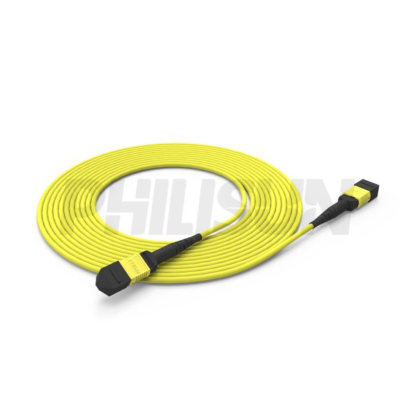
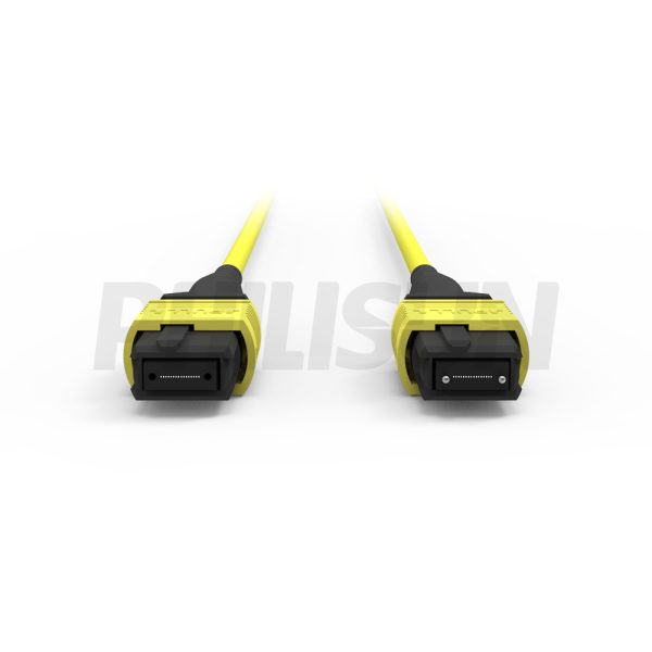
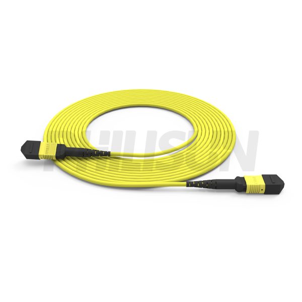
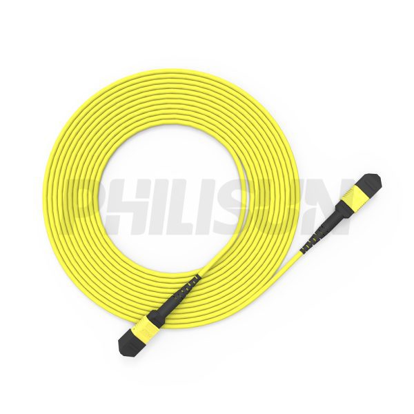
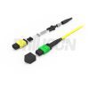
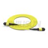
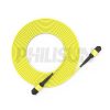
MPO-16 Fiber Optic Cable – MPO to MPO OS2 Singlemode, 16-Fiber Jumper Cord, for 800G QSFP-DD & 800G OSFP DR8, APC Polish (Female/Male), Type B, Yellow
800G QSFPDD
800G OSFP DR8
- High Quality
- Factory Outlet
- Satisfaction Guarantee
- Global Shipping
| SPECIFICATIONS | |||
|---|---|---|---|
| Connector A | MPO | Connector B | MPO |
| Fiber type | G657A1 | Fiber number | 16 Fibers |
| MPO IL | Standard loss/low loss | Polishing | APC |
| Connector housing color | Yellow/Green | Connector boot type | Round/ribbon/bare fiber |
| Connctor type | Female/Male | RL | ≥60dB(SM) |
| IL(Typical) | 0.1/0.2dB | IL(Max. value) | 0.35/0.6dB |
| Tolerance | ﹢6cm | Cable color | Yellow |
| Cable outer diameter | 3.0/3.5/4.5/5.0mm | Flame retardant grade | OFN/OFNR/OFNP |
| Cable material | LSZH/PVC/TPU | Fiber loss | 0.35db@1310nm/0.2dB@1550nm |
| Fiber brand | Corning/YOFC | Min.bending radius(long term) | 20D |
| Working wavelength | 1310/1550(SM) | Durability | ≥500 times |
| Min.bending radius(short term) | 10D | Polarity | TYPE B |
| Operating temperature | -10 to 70℃ (14 to 158℉) | Storage temperature | -40 to 85℃ (-40 to 185℉) |
PRODUCT PRESENTATION
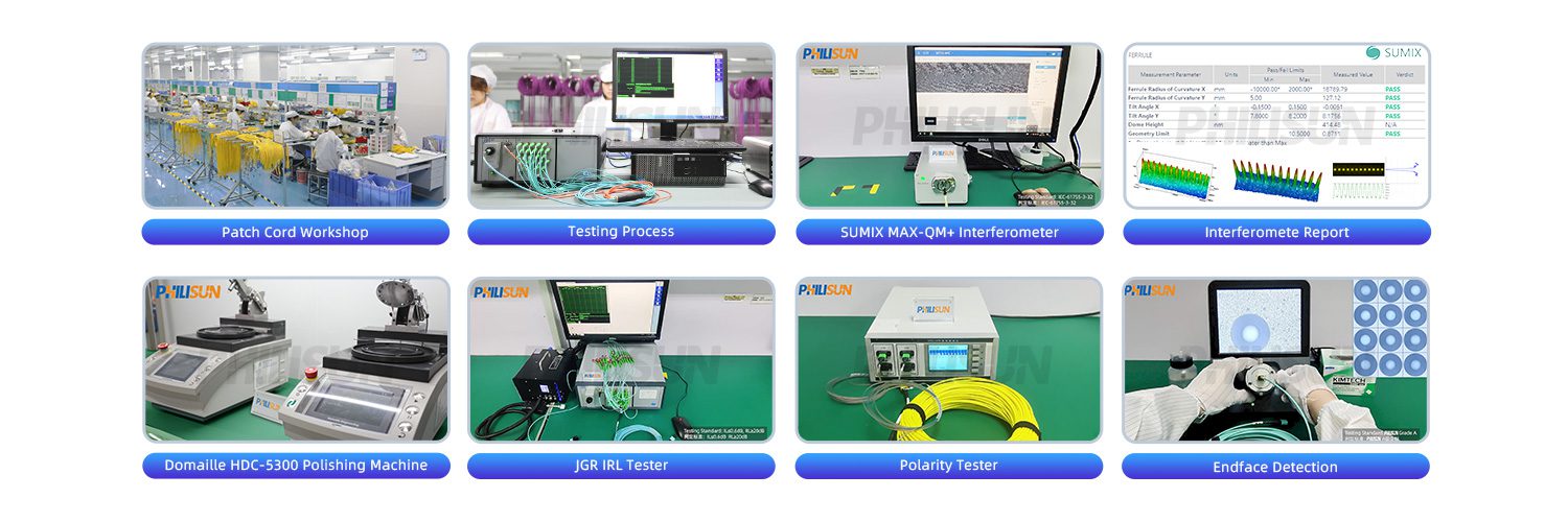
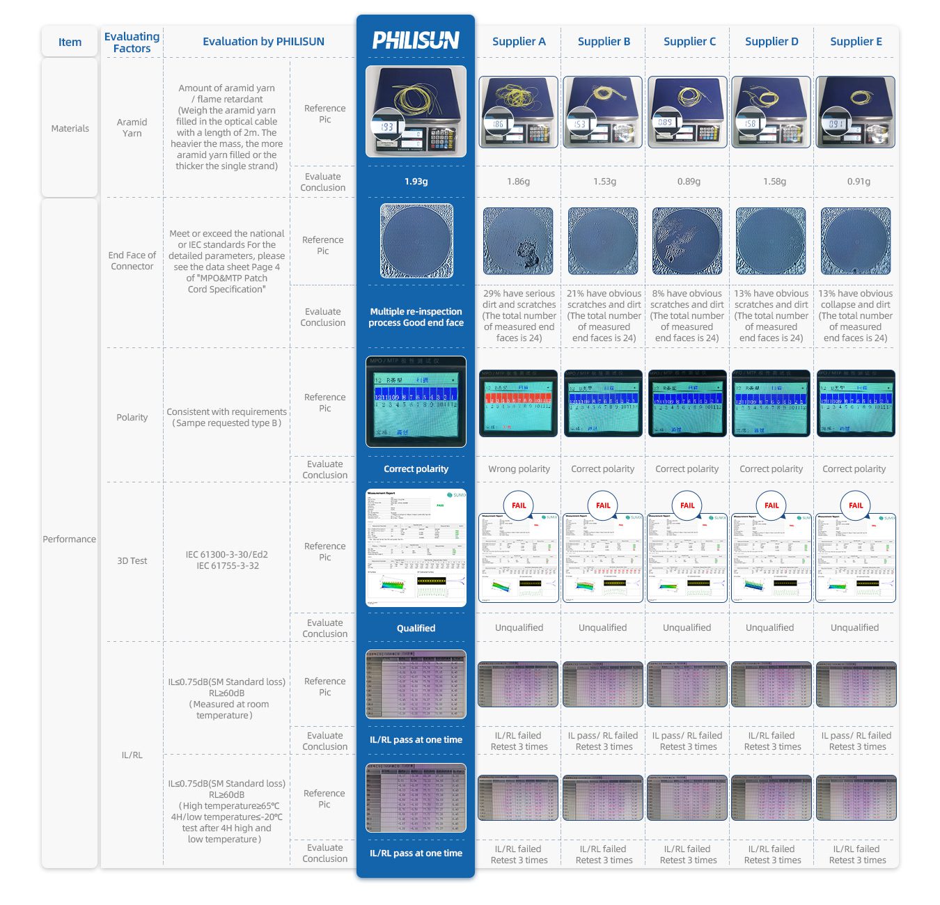
This 16-fiber MPO to MPO OS2 Singlemode fiber optic cable is specifically engineered for next-generation solutions, specifically supporting 800G QSFP-DD and 800G OSFP DR8 applications. As MPO is an optical fiber connector adopted by IEEE standard for 40G / 100G, product reliability is key. Committed to the production of fiber optical patch cord for 19 years, PHILISUN has built an experienced R & D team. This MPO cable features MPO (Female/Male) connectors with an APC polish (RL ≥60dB), available in low loss (≤0.35dB) options, supporting Type B polarity. The PHILISUN MPO patch cord is 100% tested and passes 3D IEC standard, ensuring high-performance Singlemode fiber connectivity.
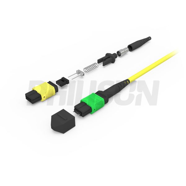
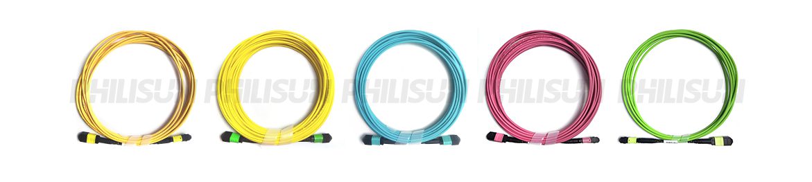
MPO SERIES PRODUCTS
Production & Testing Equipment
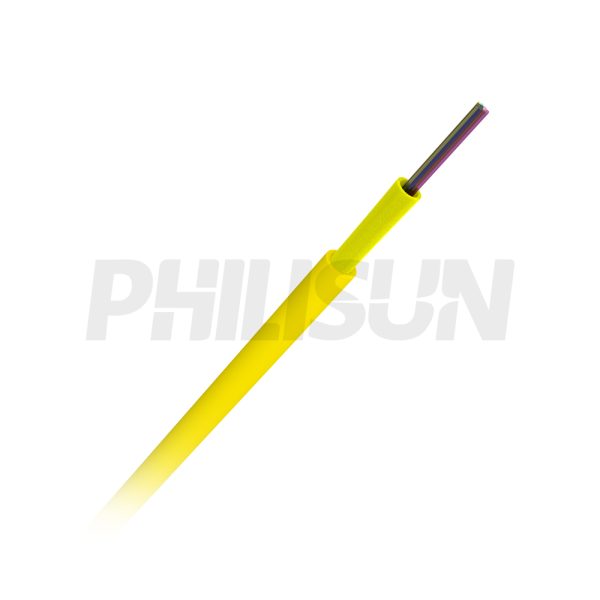
FIBER OPTIC CABLE STRUCTURE

PERFORMANCE PARAMETER
| Technical Performance | |||
|---|---|---|---|
| Ferrule type | Insertion loss | Return loss | |
| Typical | Maximum | ||
| SM standard loss | 0.20dB | ≤0.75dB | ≥ 60dB (APC 8°) |
| SM low loss | 0.10dB | ≤0.35dB | |
| MM standard loss | 0.20dB | ≤0.6dB | ≥ 20dB |
| MM low loss | 0.10dB | ≤0.35dB | |
| MT Ferrule Options | ||||||
|---|---|---|---|---|---|---|
| Fiber mode | Performance | Fiber count | ||||
| Single mode | Standard loss | 12 (1x12) | ||||
| 24 (2x12) | ||||||
| Low loss | 12 (1x12) | |||||
| Multimode | Standard loss | 12 (1x12) | ||||
| 16 (1x16) | ||||||
| 24 (2x12) | ||||||
| 32 (2x16) | ||||||
| Low loss | 12 (1x12) | |||||
| 24 (2x12) | ||||||
| Cable Parameter | ||||||||
|---|---|---|---|---|---|---|---|---|
| Items | Specifications | |||||||
| Fiber Count | 2 | 4 | 6 | 8 | 12 | 24 | ||
| Fiber | Diameter | 250±15μm | ||||||
| Color | Blue/Orange/Green/Brown/Gray/White/Red/Black/Yellow/Purple/Pink/Aqua | |||||||
| Strength Member | Aramid Yarn | |||||||
| Outer Jacket | Diameter | 3.0±0.2mm | ||||||
| Material | PVC /LSZH | |||||||
| Color | Blue/Orange/Green/Brown/Gray/White/Red/Black/Yellow/Purple/Pink/Aqua | |||||||
| Mechanical Performance | ||||||||
|---|---|---|---|---|---|---|---|---|
| Items | Specifications | |||||||
| Fiber Count | 2 | 4 | 6 | 8 | 12 | 24 | ||
| Tensile Strength (Long Term) / N | 80 | |||||||
| Tensile Strength (Short Term)/ N | 150 | |||||||
| Crush Resistance (Long Term) / N/10cm | 150 | 100 | ||||||
| Crush Resistance (Long Term) / N/10cm | 500 | |||||||
| Min. Bend Radius (Dynamic) / mm | 20D | |||||||
| Min. Bend Radius (Static)/ mm | 10D | |||||||
| Operating Temperature/℃ | -20~+60 | |||||||
| Storage Temperature/℃ | -20~+60 | |||||||
| SM Fiber Parameter | ||||||||
|---|---|---|---|---|---|---|---|---|
| Items | Unit | G.652D | G.657A1 | G.657A2 | ||||
| Mode Field Diameter | 1310nm | μm | 9.1±0.4 | 8.8±0.4 | 8.8±0.4 | |||
| 1550nm | μm | 10.4±0.5 | 9.8±0.5 | 9.8±0.5 | ||||
| Cladding Diameter | μm | 125±1 | 125±0.7 | 125±0.7 | ||||
| Cladding Non-Circularity | % | ≤1 | ≤0.7 | ≤0.7 | ||||
| Core-Cladding Concentricity Error | μm | ≤0.6 | ≤0.5 | ≤0.5 | ||||
| Coating Diameter | μm | 245±7 | 245±5 | 245±5 | ||||
| Coating Non-Circularity | % | ≤6.0 | ≤6.0 | ≤6.0 | ||||
| Cladding-Coating Concentricity Error | μm | ≤12.0 | ≤12.0 | ≤12.0 | ||||
| Cable Cutoff Wavelength | nm | λcc≤1260 | λcc≤1260 | λcc≤1260 | ||||
| Cable Attenuation Coefficient | 1310nm | dB/km | ≤0.4 | ≤0.4 | ≤0.4 | |||
| 1550nm | dB/km | ≤0.3 | ≤0.3 | ≤0.3 | ||||
| MM Fiber Parameter | ||||||||
|---|---|---|---|---|---|---|---|---|
| Items | unit | 62.5/125 | 50/125 | OM3-150 | OM3-300 | OM4 | ||
| Core Diameter | μm | 62.5±2.5 | 50±2.5 | 50±2.5 | 50±2.5 | 50±2.5 | ||
| Cladding Diameter | μm | 125±1.0 | 125±1.0 | 125±1.0 | 125±1.0 | 125±1.0 | ||
| Core Non-Circularity | % | ≤5.0 | ≤5.0 | ≤5.0 | ≤5.0 | ≤5.0 | ||
| Cladding Non-Circularity | % | ≤1.0 | ≤1.0 | ≤1.0 | ≤1.0 | ≤1.0 | ||
| Core-Cladding Concentricity Error | μm | ≤1.5 | ≤1.5 | ≤1.0 | ≤1.0 | ≤1.0 | ||
| Coating Diameter | μm | 245±7 | 245±7 | 245±7 | 245±7 | 245±7 | ||
| Coating Non-Circularity | % | ≤6.0 | ≤6.0 | ≤6.0 | ≤6.0 | ≤6.0 | ||
| Cladding-Coating Concentricity Error | μm | ≤12.0 | ≤12.0 | ≤12.0 | ≤12.0 | ≤12.0 | ||
| OFL Bandwidth | 850nm | MHz·km | ≥160 | ≥500 | ≥700 | ≥1500 | ≥3500 | |
| 1300nm | MHz·km | ≥500 | ≥500 | ≥500 | ≥500 | ≥500 | ||
| Cable Attenuation Coefficient | 850nm | dB/km | ≤3.0 | ≤3.0 | ≤3.0 | ≤3.0 | ≤3.0 | |
| 1300nm | dB/km | ≤1.0 | ≤1.0 | ≤1.0 | ≤1.0 | ≤1.0 | ||
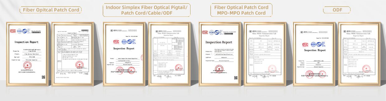
Product Certification
Quality Advantage
CONFIGURATION INFORMATION
Related products
-
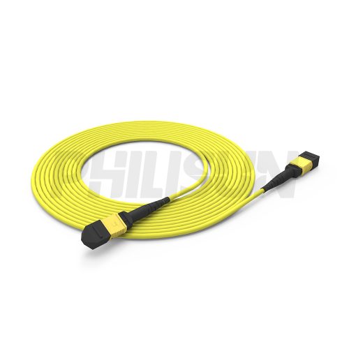
MPO-12 Fiber Optic Cable – MPO to MPO OS2 Singlemode, 12-Fiber Jumper Cord, for 800G/400G/100G Data Center, APC Polish (Female/Male), Type A/B/C, Yellow
800G OSFP(Twin-Port)
800G OSFP(Twin-Port)to 2*400G OSFP
100G to 100G QSFP28
40G to 40G QSFP+ -
MPO-8 Fiber Optic Cable – MPO to MPO OS2 Singlemode, 8-Fiber Jumper Cord, for 800G OSFP, 400G OSFP, 100G QSFP28, APC Polish (Female/Male), Type A/B, Yellow
800G OSFP(Twin-Port)
800G OSFP(Twin-Port)to 2*400G OSFP
100G to 100G QSFP28
40G to 40G QSFP+ -
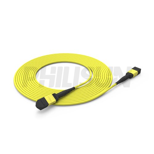
MPO-24 Fiber Optic Cable – MPO to MPO OS2 Singlemode, 24-Fiber Jumper Cord, for 10G-800G Transceivers, APC Polish (Female/Male), Type A/B/C/D/E, Yellow
10G-800G LC Duplex/Simplex transceiver Main trunk cable