What Is MPO Polarity and Why It Matters for High Speed Networks
MPO polarity refers to the correct alignment between the transmit (Tx) and receive (Rx) channels for optical signals. For a fiber link to work properly, the Tx port on one end must connect to the Rx port on the other end, and vice versa.
Unlike duplex LC patch cords, which can be reconfigured on site if wired incorrectly, MPO connectors house multiple fibers (8, 12, 24 cores, etc.). If polarity is designed incorrectly, the entire link will fail rather than just suffer from high loss or instability.
In parallel optical applications such as 40G, 100G and 400G, high density cabling and complex component layers make polarity errors costly to troubleshoot and rework. Polarity is therefore a fundamental requirement for design, procurement and deployment.
4 Basic MPO Polarity Rules to Know Before Type A, B, and C
Understanding these rules first will make it much easier to grasp the differences and logic of Type A, B and C in MPO fiber polarity design.
Fiber numbering defines the mapping relationship
Each fiber in an MPO connector has a fixed position labeled Pin 1, Pin 2, Pin 3 and so on. The core of fiber polarity is how these positions correspond at both ends of the link. In short, fiber mapping matters more than simple physical connectivity.
Key direction affects how alignment is interpreted
Common key up and key down orientations on MPO connectors directly determine fiber sequence identification and ensure consistency between diagrams and physical components. Always confirm key direction first when reviewing documents, reading cabling layouts or verifying connections on site, or Type A/B/C identification may be misleading.
Male and female connectors impact system compatibility
MPO male and female connectors differ mainly in guide pin presence. This affects not only physical mating but also overall system component compatibility. Failure to confirm male/female matching in advance can lead to connection failures, incompatible parts or incomplete system integration.
Cable Type Is Not the Same as Overall Polarity Method
Type A, B and C describe fiber mapping within a single MPO cable. \
Method A, B and C refer to the overall polarity method used across the full link.
The former applies to individual cables, while the latter governs the entire system. Even with a correct trunk cable, overall link polarity may still be wrong. Evaluation should include cassettes, adapters, patch cords and other related components.
MPO Polarity Types: Differences Between Type A, Type B and Type C
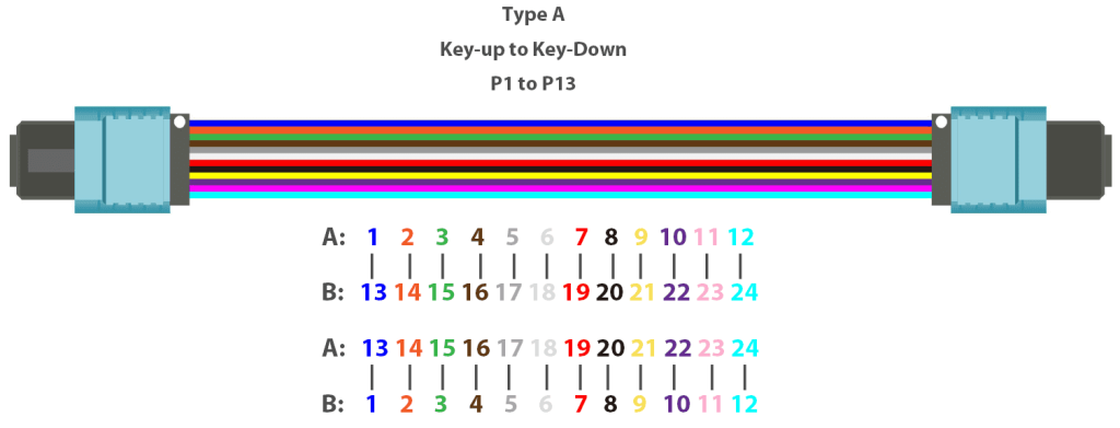
Type A: Straight Through
In Type A MPO polarity, fibers are mapped directly with Pin 1 to Pin 1 and Pin 2 to Pin 2 on opposite ends. It has a simple structure and is widely used for trunk cables and structured cabling. Cassettes or patch cords are required to complete final Tx/Rx matching.
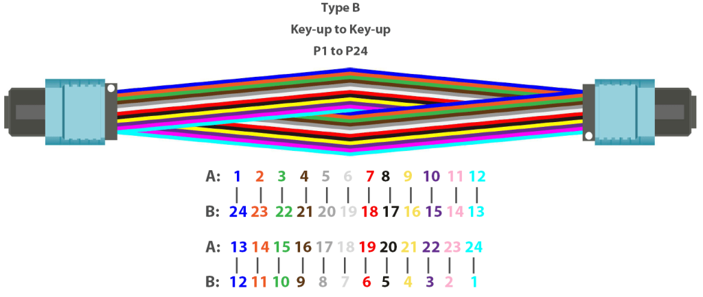
Type B: Full Reverse
In Type B MPO polarity, the fiber sequence is fully reversed at both ends. Pin 1 connects to Pin 12 and Pin 2 connects to Pin 11. It provides end to end polarity reversal and is ideal for direct MPO to MPO connections, commonly used for 40G and 100G SR4 direct links and other parallel optics applications.
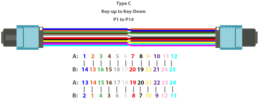
Type C: Pair Reverse
In Type C MPO polarity, adjacent fiber pairs are swapped, such as 1↔2 and 3↔4. It has more limited applications and is mostly used in specific duplex based systems, rather than as a default choice for standard data center deployment.
Type A / B / C MPO Polarity Comparison
| Type | Fiber Mapping | Reversed | Common Applications | Key Features | Notes |
| Type A | 1 to 1 straight through | No | Structured cabling, trunk links with cassettes | Simple logic, ideal for backbone extension | Does not perform Tx/Rx reversal on its own |
| Type B | 1 to 12 full reverse | Yes | Direct MPO module connections, 40G/100G parallel optics | Suitable for end to end direct links | Requires matching equipment ports and link structure |
| Type C | Adjacent fiber pair swap | Partial | Specific duplex based systems | Fits dedicated system logic | Relatively narrow application scope |
How to Choose the Right MPO Polarity
When selecting the right fiber polarity, identifying the specific link scenario is often more effective than jumping straight into a comparison of Type A, Type B, and Type C.
| Application Scenario | Typical Link Structure | Common Polarity Recommendation | Key Inspection Points | Common Pitfalls |
| Direct Switch-to-Switch Connection | MPO transceivers on both ends; no cassettes or intermediate conversions. | Type B (Most common) | Verify if it is a standard MPO-to-MPO direct link. | Using other polarity types, causing Tx/Rx misalignment. |
| Structured Cabling via Cassettes | Trunk + Cassette + Patch Cord + Adapter Panel. | Type A Trunk (paired with specific system components) | Ensure the entire link follows a unified Polarity Method (A, B, or C). | Ignoring the matching relationship between cassettes and patch cords. |
| Breakout or MPO-LC Hybrid Systems | MPO Backbone + Breakout Cable/Cassette + LC device interfaces. | Depends on specific system requirements. | Breakout method, equipment port definitions, and component compatibility. | Drawing conclusions based solely on cable type while ignoring overall link mapping logic. |
For typical direct MPO transceiver-to-transceiver connections, Type B is generally the more common choice. However, if the fiber link involves cassettes, patch cords, or breakout structures, it becomes more critical to ensure that the entire link is designed and provisioned according to a single, consistent polarity logic
How to Avoid MPO Polarity Errors: Verification and Deployment Tips
Common Errors and Symptoms
The most direct symptom of MPO polarity errors is the link failing to establish, with the device showing “Link Down.” This is often misdiagnosed as a faulty transceiver, patch cord, or hardware port. Mixing incompatible components also increases the difficulty of troubleshooting and can severely impact project delivery timelines.
Pre-deployment Polarity Testing and Verification
Before deployment, first define the link category, such as a direct connection, structured cabling setup, or a breakout system. As part of MPO polarity testing and verification, ensure that all cabling components, including trunks and cassettes, follow the same polarity logic.
Also verify that the fiber count, connector types, male/female configuration, and key orientation match the design specifications. For large-scale projects, testing a sample link first can help identify systemic issues early.
Best Practices for MPO Polarity Management
Treat MPO polarity management as a system-wide rule. Standardize the technical scheme at the start of the project and confirm component compatibility, labeling standards, and documentation in advance.
For large-scale or complex links, prioritize factory-tested pre-terminated solutions to minimize human error and simplify future maintenance or expansions.
How Integrated MPO Solutions Help Reduce Polarity Risks
For projects requiring high consistency and deployment efficiency, an integrated MPO solution is far more reliable than assembling disparate parts on site. PHILISUN provides a comprehensive range of MPO products covering various polarity types and applications, including:
- Type A / Type B / Type C MPO Trunk Cables
- MPO-LC Cassettes
- MPO Breakout Cables
- MPO Enclosures
These products support diverse network deployment needs, from direct device connections to complex structured cabling environments.
To address challenges in component matching and link verification, PHILISUN offers customized technical support tailored to your specific project. We assist in confirming fiber counts, interface types, polarity logic, and system compatibility. All solutions are delivered based on rigorous factory-tested standards, with flexible compatibility support to reduce the risk of on-site troubleshooting and costly rework.
Conclusion
The core of determining MPO polarity lies in the link structure, not the individual cable itself. When selecting cabling components, it is more important to first define the application scenario and confirm the compatibility between components than to compare Type A, Type B, and Type C in isolation.
If you need to confirm an MPO polarity scheme for an actual project, PHILISUN provides comprehensive MPO product support and deployment recommendations to help you complete your link design and selection more efficiently.
MPO Polarity FAQs
Is there a difference between MTP and MPO polarity?
There is no fundamental difference. MTP is a high-performance implementation of the MPO connector; the polarity logic remains identical.
Which polarity is usually chosen when connecting two 100G switches?
In a typical direct MPO transceiver connection (without intermediate cassettes), Type B is the most common choice. However, the final decision should always be confirmed based on the transceiver interface and the overall link structure.
Can Type A be used for high-speed networks?
Yes. Type A is not restricted to low-speed applications. It is actually better suited for use within structured cabling systems when paired with the appropriate patch cords and cassettes.
Is Type C still commonly used today?
Compared to Type A and Type B, Type C is less common. It is primarily used in specific systems and legacy duplex transitions (like 10G). Its frequency of use in modern standard data center projects is relatively low.
Can MPO polarity be modified directly on-site?
Most standard trunk cables are not designed for on-site modification, except for specialized cables with “switchable” polarity designs. It is highly recommended to confirm the polarity during the design and procurement phases.
Does the polarity logic differ between MPO-8, MPO-12, and MPO-24?
The basic principles remain consistent, as they all center on fiber mapping and Tx/Rx alignment. The only differences lie in the application scenarios and system complexity. As the fiber count increases, the planning and verification of the link become more complex.