

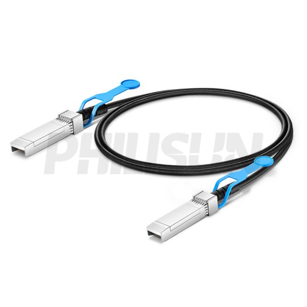
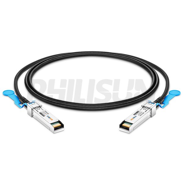


25G SFP28 to SFP28 Active Direct Attach Copper Twinax Cable (ACC)
Compliant with IEEE 802.3, SFP28 MSA, SFF-8402 standard
Switch to Switch
Switch to GPU
- High Quality
- Factory Outlet
- Satisfaction Guarantee
- Global Shipping
| SPECIFICATIONS | |||
|---|---|---|---|
| Cable End Connector A | SFP28 | Cable End Connector B | SFP28 |
| Jumper Type | Direct-Attach | Data Rate | 25G |
| Aggregate Bit Rate | 25.78125Gbps | Lane Bit Rate | 25.78125Gbps |
| Number of Channels | 1 | Single Channel Rate | 25G |
| Minimum Bend Radius | 5X Cable OD -Single, 10X Cable OD - Repeated | Factory Brand | PHILISUN |
| Attenuation | 26AWG:10dB/8.5m maximum 28AWG:10dB/7m maximum 30AWG:8.4dB/5.5m maximum | Bit Error Rate | ≤10-12 |
| Shield | Braid/Foil | Wire AWG | 26AWG/28AWG/30AWG |
| Cable Type | Active Twinax | Cable OD | 30AWG: 4.5mm 28AWG: 4.8mm 26AWG: 5.6mm |
| Cable Colour/Material | Black PVC(OFNR) | Cable Length Selection | 1-9 meter |
| Protocols | SFF-8402/IEEE802.3/SFF 8472/SFP28 MSA | Application Scenarios | 25 Gigabit Ethernet (25GbE) |
| Supply Voltage | 3.3V | Power Dissipation | <0.5W |
| Operating Temperature | 0 to 70℃ (32 to 158℉) | Storage Temperature | -40 to 85℃ (-40 to 185℉) |
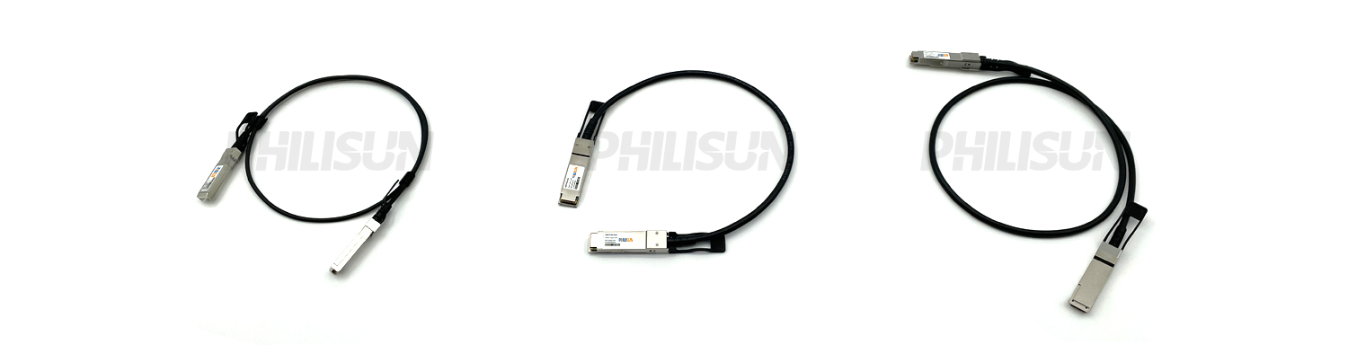
PRODUCT PRESENTATION
The PHILISUN 25G SFP28 to SFP28 Active Twinax Cable is designed for 25G Ethernet applications. It complies with IEEE 802.3 and SFP28 MSA standards. Each SFP28 connector integrates an EEPROM that stores product information readable by the host system.
These cables are ideal for very short‑reach links, offering a cost‑effective solution for 25G connections within and between adjacent racks, connecting to 25G SFP28 ports on switches and routers.
These cables are ideal for very short‑reach links, offering a cost‑effective solution for 25G connections within and between adjacent racks, connecting to 25G SFP28 ports on switches and routers.
DAC SERIES PRODUCTS
PRODUCTION & TESTING EQUIPMENT

PERFORMANCE PARAMETER
| Absolute Maximum Ratings | |||||||||
| Parameter | Unit | Min. | Typical | Max. | Notes | ||||
| Storage Temperature | ℃ | -40 | – | 85 | – | ||||
| Operating Relative Humidity | % | – | – | 85 | – | ||||
| Power Supply Working Voltage | V | -0.5 | – | 3.63 | – | ||||
| Recommended Operating Conditions | |||||||||
| Parameter | Unit | Min. | Typical | Max. | Notes | ||||
| Operating Case Temperature | ℃ | 0 | – | 70 | – | ||||
| Power Supply Working Voltage | V | 3.135 | 3.135 | 3.135 | – | ||||
| Bit Rate | Gbps | – | 25.78125 | – | – | ||||
| Electrical Characteristics | |||||||||
| Parameter | Unit | Min. | Typical | Max. | Notes | ||||
| Differential Impedance | Ω | 90 | 100 | 110 | 1 | ||||
| Differential Insertion Loss SDD21 | – | -22.48d B Min. @ 12.89GHz | – | ||||||
| Intra- Pair Skew | ps/m | – | – | 15 | 2 | ||||
| NEXT | dB | – | – | -35 | – | ||||
| COM | dB | 4 | – | – | – | ||||
| Dielectric Withstand Voltage | VDC | 300 | – | – | 3 | ||||
| Insulation Resistance | MΩ | 10 | – | – | 4 | ||||
| Low Level Contact Resistance | Milliohms | – | – | 70 | 5 | ||||
| Note: 1. Test condition: Rise time of 25ps (20 % – 80 %), cable termination. 2. 10MHz≤f ≤ 19GHz. 3. EIA-364-20: Apply a voltage of 300 VDC for 1 minutebetween adjacent terminals, and between adjacent terminals and ground. 4. EIA364-21: AC 300V 1 minute. 5. EIA-364-23: Apply a maximum voltage of 20mV, and a current of 100 mA. |
|||||||||
| Performance Specification | |||||||||
| All performance is defined over the recommended operating environment unless otherwise specified. | |||||||||
| 1. Cable | |||||||||
| Parameter | Typical | ||||||||
| Wire Gauge | AWG30/AWG28/AWG26 | ||||||||
| Impedance | 100±5Ω | ||||||||
| Construction | Twin-Axial | ||||||||
| Jacket Type | PVC | ||||||||
| Bend Radius | 5X Cable OD -Single, 10X Cable OD – Repeated | ||||||||
| 2. Plug | |||||||||
| Parameter | Typical | ||||||||
| Backshell Material | Nickel- Plated Zinc Diecast | ||||||||
| Contact Material | PCB with Gold- Plated Pads | ||||||||
| Latch | Positive Latching w/Pull Tab | ||||||||
| Insertion Force | 18N Max. | ||||||||
| Withdrawal Force | 12.5N Max. | ||||||||
| Retention Force | 90N Min. | ||||||||
| Durability | 50 Cycles Min. | ||||||||
PIN Function Definitions
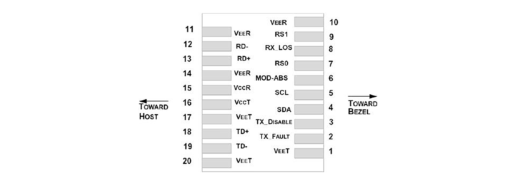
Transceiver Pin Descriptions
| Pin No. | Symbol | Level/ Logic | Description | ||||||
| 1 | VeeT | – | Module Transmitter Ground | ||||||
| 2 | Tx_Fault | LVTTL-O | Module Transmitter Fault Indication | ||||||
| 3 | Tx_DIS | LVTTL-I | Transmitter Disable, Active High Disable Transmitter Output | ||||||
| 4 | SDA | LVTTL-I | 2-Wire Serial Interface Data Line | ||||||
| 5 | SCL | LVTTL-I/O | 2-Wire Serial Interface Clock | ||||||
| 6 | MOD_ABS | LVTTL-O | Module Absent, Connected to Ground in The Module | ||||||
| 7 | RS0 | – | Rate Select0,Optionally Controls SFP28 Module Receiver | ||||||
| 8 | RX_LOS | LVTTL-O | Loss of Receiver Signal Indication | ||||||
| 9 | RS1 | – | Rate Select 1, Optionally Controls SFP28 Module Transmitter | ||||||
| 10 | VeeR | – | Module Receiver Ground | ||||||
| 11 | VeeR | – | Module Receiver Ground | ||||||
| 12 | RD- | CML-O | Receiver Inverted Data Output | ||||||
| 13 | RD+ | CML-O | Receiver Non-Inverted Data Output | ||||||
| 14 | VeeR | – | Module Receiver Ground | ||||||
| 15 | VccR | – | Module Receiver 3.3V Supply | ||||||
| 16 | VccT | – | Module Transmitter 3.3V Supply | ||||||
| 17 | VeeT | – | Module Transmitter Ground | ||||||
| 18 | TD+ | CML-I | Transmitter Non-Inverted Data Input | ||||||
| 19 | TD- | CML-I | Transmitter Inverted Data Input | ||||||
| 20 | VeeT | – | Module Transmitter Ground | ||||||
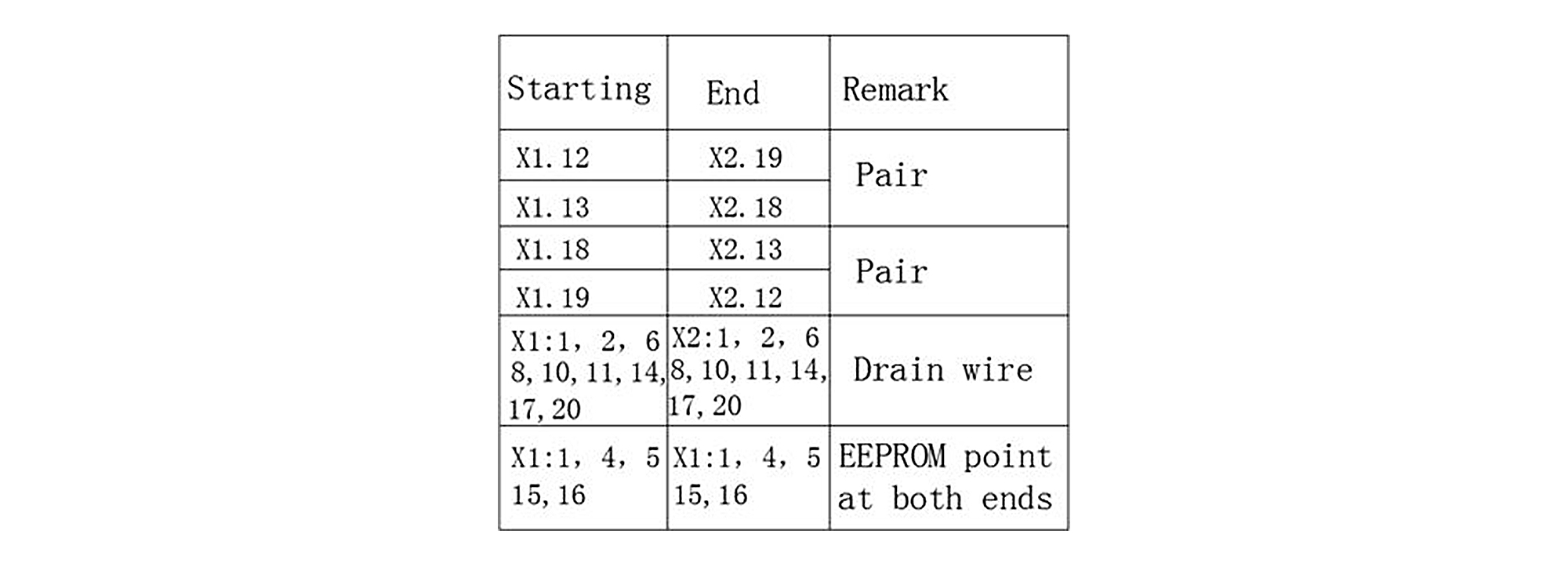
Recommended Wiring Diagram
PRODUCT CERTIFICATION

COMPATIBLE BRANDS

CONFIGURATION INFORMATION