In high-speed network construction, a common question arises: why does the user experience still feel “laggy” even after upgrading bandwidth from 10G to 100G or even 400G? In many cases, the issue is not bandwidth alone, but fiber latency.
For AI clusters, High-Performance Computing (HPC), and high-frequency trading (HFT), factors like signal propagation, Forward Error Correction (FEC), device hop counts, and excess cable length can become real bottlenecks for interconnect efficiency in low latency networks.
This guide explains what fiber optic latency is, how to calculate fiber latency, the differences between interconnect solutions, and strategies for low-latency network optimization.
Understanding Fiber Optic Latency: Why Do High-Speed Networks Still Lag?
Defining Fiber Optic Latency
Fiber latency is the time it takes for data to travel from the transmitter into the optical link and reach the receiver. It is not caused by a single factor but is the cumulative result of signal propagation, component processing, and network architecture.
Bandwidth vs. Latency: What’s the Difference?
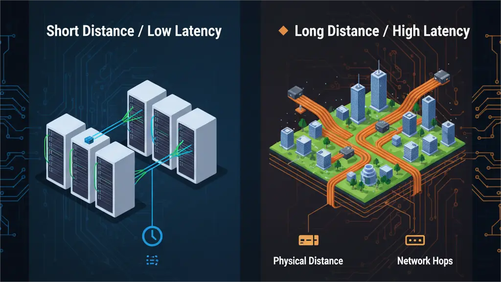
Bandwidth vs. latency is a critical distinction in high-speed network design. Bandwidth measures how much data can be transmitted per unit of time, whereas latency measures how fast that data arrives. A link can have massive bandwidth, but if the path is too long or involves too many processing steps, the response time will remain poor. For real-time applications, fiber latency is often a more critical metric than raw bandwidth.
Which Applications Are Most Latency Sensitive?
- AI Clusters & GPU Interconnects: Node-to-node communication is constant in large-scale training environments. Low-latency interconnects help reduce wait time between nodes, improving performance in AI clusters and high-speed GPU interconnect.
- High-Performance Computing (HPC): HPC workloads rely on parallel processing and tight synchronization. Small delays in individual communications are magnified across thousands of cycles, making stable, low-latency performance essential.
- High-Frequency Trading (HFT): In high-frequency trading (HFT) networks, a difference of just a few microseconds can affect execution outcomes. Every meter of cable and every switch hop is therefore optimized to reduce delay.
What Determines Fiber Optic Latency?
Propagation Delay in Optical Fiber
The most fundamental source of latency is the time light takes to travel through the fiber core. Light travels at approximately 300,000 km/s in a vacuum, but it slows down when entering glass due to the refractive index.
Since this is a physical property, it cannot be eliminated; it can only be managed by shortening the physical path.
Transceiver Processing Delay
Transceiver processing delay is introduced during the Electrical-to-Optical (E-O) and Optical-to-Electrical (O-E) conversion performed by optical modules. While this transceiver latency usually ranges from a few nanoseconds to tens of nanoseconds, it remains a relevant factor in ultra-low latency environments.
How FEC Adds Latency
FEC latency is a major contributor to delay in high-speed links. While Forward Error Correction improves reliability by correcting bit errors without retransmission, the encoding and decoding process takes time.
For 100G, 400G, and higher rates, this forward error correction latency can become significant.
Engineers must often balance the need for link stability against the latency penalties of specific FEC algorithms.
Switch Hops and Network Topology
End-to-end latency is heavily influenced by the number of “hops” in a network. Each switch or intermediate connection adds processing overhead. Streamlining the network topology to reduce unnecessary forwarding is a primary goal for low-latency
How to Calculate Fiber Optic Latency: Why Theoretical and Actual Values Differ
Estimating Fiber Propagation Delay
From an engineering perspective, fiber propagation delay is typically estimated at 5 nanoseconds per meter (5 ns/m). This figure represents the typical speed of light within standard optical fiber. As a result, one-way delay increases linearly with distance, making total cable length the most fundamental parameter when you need to calculate fiber latency.
Fiber Latency Examples: 100m, 500m, and 1km
To visualize these calculations, consider the following estimates for standard fiber links:
| Fiber Length | One-Way Propagation Delay | Round-Trip Time (RTT) |
| 100 Meters | Approx. 0.5 µs | Approx. 1 µs |
| 500 Meters | Approx. 2.5 µs | Approx. 5 µs |
| 1 Kilometer | Approx. 5 µs | Approx. 10 µs |
| 10 Kilometers | Approx. 50 µs | Approx. 100 µs |
These benchmarks are useful for preliminary planning, especially when comparing different link distance strategies or basic interconnect options.
Why Theoretical Propagation Isn’t the Same as Actual Link Latency
Theoretical propagation delay only measures the time of flight for light within the glass. It does not represent actual link latency in a live production environment.
In a real-world network, you must also account for transceiver processing, FEC (Forward Error Correction) encoding and decoding, switch forwarding, buffer queuing, and the application protocol stack. While theoretical values help establish the baseline delay caused by distance, they cannot be used as the final end-to-end latency metric.
Single-Mode vs. Multi-Mode: Is There a Significant Latency Difference?
Users often ask whether single-mode vs. multi-mode latency differs in a meaningful way. In most practical engineering scenarios, this is rarely the deciding factor.
While there are subtle differences in propagation characteristics between the two, the gap is usually negligible within the distances typical of data centers and enterprise networks. Factors such as total link length, transceiver design, FEC settings, and network topology generally have a much greater impact on performance. Choosing between single-mode and multi-mode should therefore be based on transmission distance, speed requirements, architecture, and budget.
DAC, AOC, or Fiber: Which Is Better for Low-Latency Interconnects?
In low-latency interconnects, DAC, AOC, and transceiver + fiber solutions each have specific roles. The right choice depends on whether the connection is within a rack, across rows, or part of a high-density backbone.
| Solution | Typical Distance | Latency Characteristics | Key Advantages | Best Use Case |
| DAC | Ultra-Short | Direct electrical connection with minimal overhead | Simple design and high-speed efficiency | Server-to-ToR switch or adjacent rack connections |
| AOC | Short to Medium | Balanced performance based on specific IC design | Lightweight and flexible for high-speed routing | High-speed interconnects for GPUs and switches |
| Transceiver + Fiber | Long Distance | Consistent stability across complex infrastructures | High scalability and easier maintenance | Cross-rack, cross-zone, and high-density backbone cabling |
When selecting a solution, it is important to look beyond a single latency figure. Successful deployment requires a balanced evaluation of distance, cable management, port density, and future scalability.
How to Build a Low-Latency Fiber Network: Fiber Optic Latency Optimization and Solution Selection
The core of low-latency network optimization lies in simplifying the link architecture and controlling key configurations. During deployment, signal paths should be kept as short as possible by reducing unnecessary cable slack and redundant links. Device hops and intermediate connection points also need to be controlled, since extra patching stages or additional hardware increase overall overhead.
In high-speed links, optical transceiver and FEC configuration choices also need careful evaluation. Different transceiver designs vary in processing speed, while FEC improves reliability at the cost of added latency. Effective link optimization depends on balancing response time requirements with the level of stability needed in actual deployment.
Fiber and Transceiver Solutions for Low-Latency Networks
Selecting the right solution depends on link distance, interface speed, and cabling structure. To support these network deployment needs, PhiliSun provides product options for short-reach interconnects, high-speed links, and high-density backbone cabling.
AOC & DAC Solutions for Short-Range Interconnects
For connections within a rack or between adjacent racks, PhiliSun provides AOC and DAC solutions suitable for high-performance links between servers, switches, and GPUs.
High-Speed Optical Transceivers for Network Upgrades
For networks that require higher throughput and greater scalability, PhiliSun offers 100G, 200G, and 400G optical transceivers for switching layers, backbone links, and other high-speed interconnect scenarios.
MPO Solutions for High-Density Backbone Cabling
For environments that require dense backbone infrastructure and cleaner link management, PhiliSun provides MPO trunk and MPO breakout solutions suited for structured cabling and high-density backbone links.
Critical Support for Low-Latency Deployments
Final performance also depends on compatibility, validation, and deployment support. PhiliSun focuses on four key areas to support successful integration:
Tested for Reliable Performance
Every optical component undergoes validation to support the stability and link consistency required for high-speed interconnects.
Broad Multi-Brand Compatibility
Our solutions support mainstream platforms and diverse hardware environments, simplifying deployment across complex network architectures.
Flexible Customization Support
We provide tailored configurations for interfaces, lengths, compatibility coding, and cabling structures to fit specific site requirements.
Professional Technical Support
Our team provides targeted assistance with product selection, link matching, and deployment planning.
In practice, low-latency deployment works best when AOC, DAC, high-speed transceivers, and MPO cabling are matched to the actual link scenario.
Conclusion
For high-speed network deployment, fiber latency should not be treated as something to evaluate later. It needs to be considered early in the link planning process. In many cases, choosing the right interconnect solution and keeping the link structure efficient will do more to improve real-world performance than simply increasing bandwidth.
If you are evaluating interconnect options for a data center, AI cluster, or HPC environment, PhiliSun can support your low-latency deployment with the right optical transceivers, high-speed interconnect solutions, and MPO cabling options.
FAQs about Fiber Optic Latency
How much latency does 1 km of fiber add?
As a common engineering estimate, 1 kilometer of fiber adds about 5 microseconds of one-way propagation delay, or about 10 microseconds round trip. In real applications, total fiber optic latency will also include transceiver processing, FEC, and device forwarding overhead.
Does fiber optic reduce latency?
In many network scenarios, fiber can help deliver lower and more stable latency, especially in longer-reach, higher-speed, and high-density interconnect environments. However, latency is not determined by the transmission medium alone. Optical module processing, FEC, device hops, and link structure all affect the final result.
Does FEC increase network latency?
Yes. FEC improves link reliability by adding encoding and decoding processes, but that also introduces extra delay. In high-speed networks, FEC latency should be included in the overall evaluation.
Is DAC always lower latency than fiber?
Not always. DAC often has an advantage in ultra-short-reach connections, but once the network involves longer distances, higher density, or more complex structured cabling, fiber-based solutions are often the better fit. When comparing DAC vs fiber latency, the right choice depends on the actual link scenario.
Does fiber length affect ping?
Yes. The longer the fiber link, the higher the propagation delay, so cable length does affect round-trip time. However, ping is not determined by fiber length alone. Device forwarding, network path design, and congestion can also influence the final latency.
Need help designing a low-latency fiber link? PHILISUN can help you choose suitable optical transceivers, AOC/DAC cables, and fiber cabling solutions. Contact us for a practical interconnect recommendation.