

Quick answer: an SFP module not recognized message is not the same as a link-down alarm. First decide whether the host cannot read or accept the module, the module is present but the link stays down, or the link comes up and then flaps. Those three symptoms lead to different checks.
- Not detected or rejected: save the exact log and inventory output, then check seating, EEPROM identity, platform coding, host policy and the device support matrix.
- Detected but link down: check administrative state, port speed, lane or breakout mode, the two end modules, and the optical or cable path.
- Link flaps: review DOM/DDM, temperature, errors and optical power, then inspect and clean separable fiber connections before cross-testing.
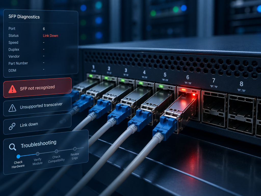
Diagnose the Symptom Before Replacing the Module
A pluggable can fail at several layers. The switch or adapter may not read the module management interface. It may read the identity but reject the part under its compatibility policy. It may enable the module while the electrical lane mode, optic, fiber, or far-end configuration prevents link. Replacing hardware before identifying the layer can hide the evidence and repeat the same failure.
Start with a timestamped evidence set: device brand and exact model, interface name, operating system or firmware release, module vendor and part number, the full error text, interface state, and any transceiver inventory or diagnostics output. If the host reports no module at all, note that separately from an “unsupported” warning. If you need form-factor background, use the SFP optical module guide; this page stays focused on fault isolation.
Also record what changed. A new module, software upgrade, breakout change, patch-cord move, or maintenance window is more useful than a general statement that the link “stopped working.” Keep the original module and cable available until the comparison is complete.
SFP Module Not Recognized: 7-Step Troubleshooting Process
Step 1: Classify the Symptom and Save the Evidence
Read the interface log and hardware inventory before reseating anything. “Not present,” “unsupported transceiver,” “link down,” “loss of signal,” and repeated up/down events are different observations. Save the interface configuration and transceiver detail output while the fault is active. If the platform exposes EEPROM fields, record the identifier, vendor name or OUI, part number, revision, serial number, wavelength and compliance code. Do not edit those fields during diagnosis.
Then confirm the affected scope. One bad module, every port in a line card, one breakout group, or both ends after a software version change suggest different causes. A single clean evidence set gives the device vendor or optics supplier something reproducible to review.
Step 2: Reseat the Module and Inspect the Port
Follow the hardware guide to shut or isolate the interface when required. Remove the module by its latch, inspect the cage and module contacts for damage or debris, and reinstall it fully. A partially seated module can prevent the host from reading the management interface. Test another supported port only if that move is allowed and the port has a matching mode.
Do not confuse cage contact with the optical end face. A dirty LC or MPO connection can block or weaken light, but it normally does not explain why the host cannot read the module identity. Keep dust caps on disconnected optics and fibers. Never look into a fiber or optical bore.
Step 3: Check Coding, Host Policy and Software Support
Compare the exact module or cable part number with the platform vendor’s compatibility tool or release documentation. A standardized memory map lets a host read module data, but it does not require every platform to accept every part. Some systems validate vendor fields, compliance codes, power class, module revision, or an approved-parts list. Behavior can also differ by chassis, line card, adapter, operating system and software version.
If the error appeared after an upgrade, check the release notes and known issues before changing hardware. Use only a vendor-approved firmware or transceiver-firmware procedure for the exact models involved; such work can be disruptive. Do not copy an unsupported-transceiver override from another platform, and do not rewrite the EEPROM during fault isolation. If recoding is appropriate, the supplier should base it on the saved host and module evidence.
Step 4: Verify Port Speed, Lane Mode and Breakout
Confirm that the interface is administratively enabled and that its configured speed matches a mode supported by the port and module. A cage that accepts an SFP-family part does not prove that every speed is supported. Combo ports, adapters, multi-rate optics and high-speed cages can have platform-specific rules for auto-negotiation, FEC, lane width and downshifting. The SFP port guide explains the physical role; the device manual remains authoritative for the actual configuration.
For a splitter cable or parallel optic, verify native versus breakout mode, the number and speed of child interfaces, lane mapping, and the far-end configuration. A 100G port split into four lanes must be configured consistently with the four endpoints; plugging in a breakout cable does not create that configuration automatically.
Step 5: Match the Optic or Cable to the Link
For removable optics, compare the standard and part number at both ends. Match line rate, wavelength, reach, single-mode or multimode fiber type, connector, polarity and supported fiber length. Duplex links need transmit on one end to reach receive on the other. BiDi modules must be a complementary wavelength pair. Parallel optics require the correct MPO type, fiber count and polarity method. A link can remain down even when both hosts recognize their modules.
For DAC or AOC assemblies, collect the cable part number, length, protocol, native or split topology, and both endpoints. These are complete cable assemblies, so do not apply LC/MPO cleaning steps to sealed ends. Confirm the cable in the host compatibility information and verify each breakout leg maps to the intended port. The AOC and DAC cable range provides product context, but the deployment still needs exact endpoint qualification.
Step 6: Read DOM/DDM and Inspect the Fiber Path
If diagnostics are available, record temperature, supply voltage, laser bias, transmit power, receive power, alarms and the module’s own high/low threshold values. Compare the live reading with that module or platform table. There is no single dBm number that is correct for every SR, LR, BiDi, CWDM or higher-speed optic. A low receive reading can point to the far-end transmitter, excessive loss, contamination, a bend, a damaged connector, wrong reach, or an incorrect fiber path.
For separable fiber, follow an inspect-clean-reinspect process with approved tools and laser-safety procedures. Inspect the end face, clean only when needed, reinspect, and mate clean connectors promptly. If the host shows no DOM/DDM, check whether the module and platform expose diagnostics before declaring the module faulty. Correlate readings with interface errors, logs and the known-good test.
Step 7: Cross-Test, Then Recode or Replace
Change one variable at a time. Test the suspect module in a known-good compatible port, a known-good supported module in the suspect port, and—when the module is recognized—the original optic across a known-good fiber path. For DAC/AOC, test a known-good qualified assembly with the same endpoint and port-mode requirements. Record whether the fault follows the module, port, cable, far end, or configuration.
Replace the module when the failure follows it after identity, configuration and path checks. Request platform-specific coding when the module hardware and optical specification are correct but the saved inventory or warning shows a coding mismatch. Escalate to the device vendor when a supported part fails across ports or after a documented software change.
Error-to-Action Quick Reference
| Symptom | Likely layer | Evidence to collect | Next safe action |
|---|---|---|---|
| Module absent from inventory | Seating, cage contact, management interface or hardware | Inventory before/after reseat, port test, module part number | Cross-test one known-good supported module and port |
| Unsupported transceiver warning | Coding, approved-parts policy or software support | Full log, EEPROM identity, host model and software version | Check the exact support matrix; ask for validated coding if appropriate |
| Module present, link down | Port mode, far-end configuration, optic or cable path | Admin state, speed, breakout, both-end part numbers and link state | Correct one configuration or link-component mismatch at a time |
| Low Rx power or loss of signal | Far-end transmit, loss, contamination, polarity or wrong optic | Module thresholds, Tx/Rx readings, fiber route and end-face inspection | Inspect-clean-reinspect, then test a known-good path |
| Link flaps or errors rise | Marginal signal, temperature, cable, port or software interaction | Time-correlated DOM/DDM, error counters, temperature and change history | Isolate whether the fault follows the module, path or port |
What DOM/DDM Can and Cannot Tell You
DOM/DDM is evidence, not a pass/fail certificate. It can show whether the host reads diagnostics, whether an alarm threshold is crossed, and whether values change with temperature or fiber moves. It cannot by itself prove traffic integrity, host approval, correct lane configuration, clean connectors, or interoperability with the far end. A module can report normal local transmit power while receiving no light, and a stable reading can coexist with an incorrect speed or protocol.
Use the installed module’s thresholds and the platform’s presentation, then compare against a known-good link. If diagnostics are missing, confirm capability and host support before replacing anything. For an important rollout, add traffic and error testing after the physical link comes up.
When to Recode or Replace the Module
Recoding is a candidate only when the module’s electrical and optical specification fits the link, the hardware is healthy, and the host evidence points to identity or platform coding. Replacement is more appropriate when the failure follows the module, diagnostics show a repeatable hardware alarm, the connector or latch is damaged, or the part cannot meet the required speed, reach, fiber or temperature specification.
Before a bulk purchase, validate a sample on the exact switch, router, NIC or adapter model and software release. Check recognition, stable link, DOM/DDM presentation, traffic errors and the intended fiber or cable path. For a broader selection checklist, see the compatible transceiver validation guide.
Need a Compatible Replacement?
If the cross-test points to the module or its coding, send a structured request rather than only the speed. Include the host brand and exact model, operating system or firmware version, interface and port mode, full error message, current module or cable part number, required speed/protocol, wavelength and reach, fiber type, connector, distance, breakout topology, and available DOM/DDM readings.
Review PHILISUN optical transceivers, then contact PHILISUN with the troubleshooting evidence for a candidate part and platform-coding review. A sample test on the real host remains the final acceptance step.
Frequently Asked Questions
Why Does a Switch Say Unsupported Transceiver?
The switch may be comparing module identity or compliance fields with a platform policy, approved-parts list, line-card capability or software support table. Save the exact warning and EEPROM inventory, then check the vendor documentation for that model and release. The message does not by itself prove that the optical engine is defective.
Can a Correctly Coded Module Still Stay Link Down?
Yes. Recognition only establishes that the host can read and accept the module. The link can still fail because of administrative state, speed, FEC, lane or breakout mode, far-end configuration, wavelength pairing, fiber type, connector, polarity, distance, loss, or a faulty path.
Does Missing DOM/DDM Data Mean the Module Is Faulty?
Not necessarily. Diagnostics must be supported and exposed by both the module and host software. Check the module data sheet and platform command behavior, then use logs, inventory, link state and cross-testing. Missing diagnostics is a clue to investigate, not a standalone hardware verdict.
Can One Compatible SFP Work Across Different Switch Brands or Models?
It may work across more than one validated platform, but do not assume that form factor and speed are enough. Different hosts can apply different coding, power, software and port-mode rules. Provide every target model and release, verify the supplier’s coding plan, and sample-test each platform family before rollout.