The most critical piece of performance data on your 400G network doesn’t come from an OTDR trace—it comes from a visual check. In the seconds it takes to glance at a cable jacket or a connector housing, you are reading the visual DNA of your fiber: its fiber type, its maximum bandwidth, and its polish standard. Misinterpreting this visual data is the quickest route to catastrophic link failure. This is the definitive guide to reading the performance-critical color codes on your fiber optic components.
1. Core Standards Review: The TIA-598-D 12-Fiber Color Code
Why do all fiber technicians need to memorize the 12-color sequence? The primary function of the fiber optic color code, specifically the TIA-598-D standard, is to provide a systematic method for identifying individual fiber strands within a cable, ensuring correct end-to-end connectivity during splicing and termination.
The Sequence and Grouping Logic
The standard mandates a 12-color sequence for the fiber coating, which is repeated when the cable contains more than 12 fibers.
The Sequence:
- Blue, 2. Orange, 3. Green, 4. Brown, 5. Slate, 6. White, 7. Red, 8. Black, 9. Yellow, 10. Violet, 11. Rose, 12. Aqua/Turquoise.
For cables exceeding 12 fibers, such as those with 24, 48, or 144 cores, the sequence is repeated. To distinguish between groups, the fiber coatings in the second group (fibers 13–24) typically receive a black tracer/stripe or the buffer tubes themselves follow a color code repetition pattern. This standardized system is essential for minimizing errors during the termination of high-core-count cables.
2. The Crucial Distinction: Jacket Color vs. Fiber Core Color
Does a fiber optic cable’s jacket color tell the full story about its performance? Absolutely. While the 12-fiber sequence identifies the strand position, the cable jacket color is the mandatory indicator of the optical fiber type and, crucially, its performance capability.
Jacket Color Defined by Performance
Jacket colors are essential for installation and inventory management as they instantly identify the maximum supported speed and distance.
| Jacket Color | Fiber Type | Performance Standard | Typical Application |
| Yellow | Single Mode (OS2) | High-speed, Long-Haul | 10G, 40G, 100G, 400G/800G |
| Orange | Multimode (OM1/OM2) | Legacy Low Bandwidth | 100Mbps, 1G |
| Aqua | Multimode (OM3) | 10G Enhanced | 40G up to 150m |
| Violet/Erika Blue | Multimode (OM4) | High Performance | 40G/100G up to 400m |
| Lime Green | Multimode (OM5) | Wideband Multimode | SWDM for 40G, 100G, 400G |
This matrix clearly shows that while yellow indicates the highest distance capability (Single Mode), Violet and Lime Green indicate the highest multi-mode bandwidth capability, critical for modern data center aggregation links.
3. Decoding Connector Body and Ferrule Colors for Performance and Polish
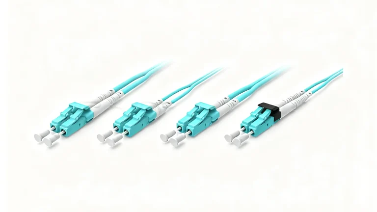
How do connector body colors indicate performance, and how do ferrule colors prevent mating errors? Connector colors serve two distinct purposes: identifying fiber type and identifying the ferrule polish angle.
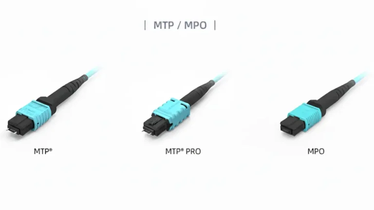
3.1 Connector Body Colors (MPO/MTP)
For high-density fiber like MPO/MTP assemblies, the color of the plastic connector body itself typically corresponds directly to the fiber type, matching the jacket color for instant identification in a crowded rack. A violet MPO connector, for instance, immediately signals that the assembly contains OM4 fiber.
3.2 Ferrule Polish Colors (Single Mode Critical)
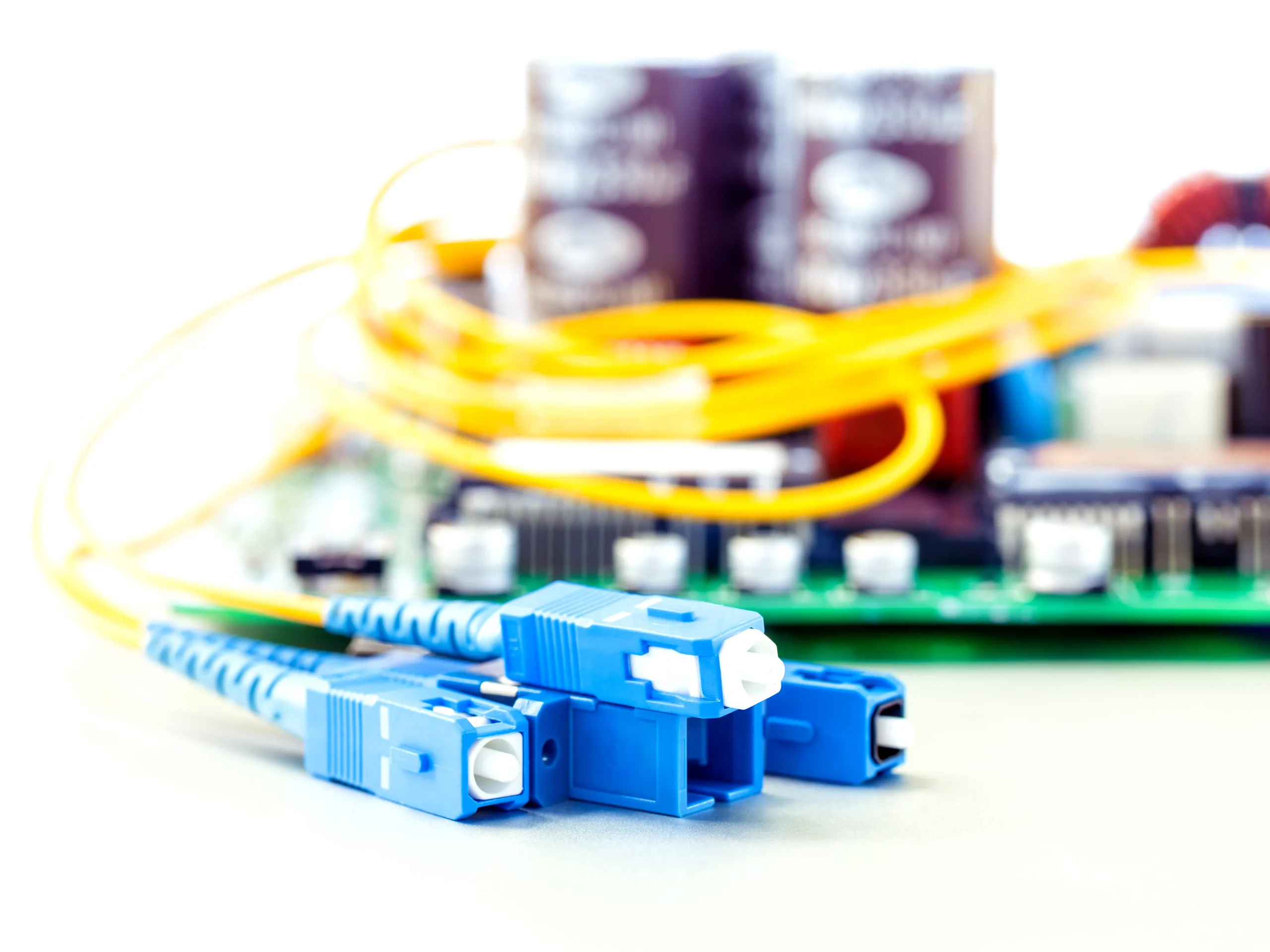
In Single Mode (OS2) links, the color of the plastic housing around the ferrule is used to prevent disastrous mating errors:
- Blue (UPC): Indicates a UPC (Ultra Physical Contact) finish, where the end-face is polished flat. This is common for general single mode links.
- Green (APC): Indicates an APC (Angled Physical Contact) finish, where the end-face is polished at an 8^{\circ angle. This finish is mandatory for high-power laser applications (like WDM, Coherent Optics, or FTTx) because the angle minimizes back-reflection, which can destabilize sensitive transceivers.
Critical Warning: Attempting to mate a Green (APC) connector with a Blue (UPC) connector will result in massive fiber optic attenuation and severe back-reflection, leading to link failure and potential damage to the end-faces.
4. Procurement Compliance: Matching Color to 400G and 800G Speeds
Why is it vital to visually verify cable color when upgrading to 400G? The jump from 10G to 400G dramatically increases sensitivity to link loss. The proper fiber optic color code becomes a purchasing specification.
Performance Mismatch Risk
A critical risk occurs when a new high-speed transceiver (e.g., 400G QSFP-DD) is connected to a cable that is visually similar but functionally inferior. For example, connecting a 40G link to an older OM3 (Aqua) cable that exceeds the distance limitation will cause immediate BER (Bit Error Rate) issues because the cable’s bandwidth is insufficient for the signal over that length. Procurement must visually verify the correct color—such as Violet (OM4) or Lime Green (OM5)—to match the intended multi-mode transmission protocol.
The PHILISUN Advantage
High-quality suppliers like PHILISUN use strict color coding on all products (from transceivers to patch cords) to simplify component matching and guarantee performance. PHILISUN specializes in Ultra-Low Loss (ULL) single mode yellow cables and high-spec fiber optic transceivers designed for 400G and 800G links. By supplying both the cable and the transceiver, PHILISUN offers an end-to-end solution where the color code is a trusted indicator of Tier 2 certified performance standards, helping procurement teams avoid compliance risks.
5. Troubleshooting Errors: Color Code Red Flags in the Field
What visual signs indicate a major color code violation or performance error? Technicians must be trained to recognize critical color code red flags, which often point to the cause of high attenuation:
- Inconsistent Colors: Finding a mix of Yellow (OS2) and Aqua (OM3) cables within a single 10G backbone run, indicating a segment length issue.
- Polish Mismatch: A technician attempting to use a green-booted patch cord (APC) to connect to a blue-sleeved adapter port (UPC). This error guarantees excessive Insertion Loss.
- Fiber Type Confusion: In high-core cables, misreading the color sequence marker (tracer stripe) and confusing fiber #4 (Brown) with fiber #10 (Violet) can lead to a cross-connection in the MPO array.
The final mile of installation is dependent on the technician’s adherence to these visual codes to prevent errors caused by poor component mixing or handling of special fiber types like bend-insensitive fiber.
6. Conclusion
Mastering the fiber optic color code is non-negotiable for operating stable, high-speed networks. The color of the cable jacket and the connector body is a critical visual shorthand, guiding procurement, ensuring correct mating, and validating performance capability. By committing to high-quality, color-coded components and transceivers, network professionals can effectively streamline deployment and guarantee the full performance potential of 400G and 800G infrastructure. Eliminate Color Confusion, Guarantee Performance. Don’t compromise your link budget with mismatched components. PHILISUN provides a full range of color-coded, Tier 2 certified Ultra-Low Loss cables, transceivers, and patch cords for guaranteed compliance with 400G and 800G standards. Contact us to ensure your inventory is visually compliant.
7. Frequently Asked Questions (FAQ) on Color Codes
Why is the MPO connector body color often different from the cable jacket color?
The MPO connector body typically matches the fiber type (e.g., Aqua for OM3) as a hard-coded identifier. However, the outer cable jacket may be manufactured in a different color (like black or gray) for aesthetic or environmental reasons, meaning you must rely on the MPO connector body color or printed jacket text to confirm the fiber type.
What is the significance of the 13th through 24th fiber colors?
The standard TIA-598-D 12-fiber sequence is repeated for the 13th through 24th fibers. The only difference is that the second group of 12 fibers will often have an identifier, such as a black tracer/stripe or dots printed on the fiber insulation to distinguish them from the first group.
Is there a color code for bend-insensitive fiber (BIF)?
No, BIF does not have a unique, mandated color code for the jacket. However, many manufacturers use auxiliary text printing on the jacket. Furthermore, Lime Green is the color code for OM5 Wideband Multimode Fiber, which is inherently bend-insensitive and used extensively in new data center deployments.
Why is Single Mode fiber always yellow?
Yellow is the universally adopted TIA color code for OS2 (Single Mode) fiber because it offers the lowest intrinsic fiber optic attenuation and is used for the longest reach. The distinct color immediately alerts personnel that the cable is designed for long-distance, high-power transmission.