Are you struggling to manage cable density as you upgrade to 100G and 400G? Traditional LC connections create severe cable sprawl, consume excessive space, and multiply network failure points. The transition to higher speeds demands parallel optics—using multiple fibers simultaneously for transmission (Tx) and reception (Rx). This architecture makes the MPO Connector (Multi-fiber Push On) the only essential technology that solves the problem. It consolidates up to 24 fibers into a single, compact interface, fundamentally enabling high-speed parallel optics and optimizing your infrastructure footprint. This guide provides the critical knowledge on MPO Connector standards, polarity, and testing to ensure a successful network transition.
What is an MPO Connector?
The IEC-61754-7 standard defines the MPO Connector as a multi-fiber array connector. Its core innovation centers on a single plastic ferrule that holds 8, 12, 16, or 24 optical fibers, replacing the multiple ferrules found in traditional connectors. The push-pull latching mechanism allows rapid deployment and disconnects in crowded rack environments. The design relies on guide pins for precise fiber alignment, a feature critical for maintaining low signal loss across multiple mated fibers.
MPO Certifications and Standards
Two main international standards govern the MPO connector:
- IEC 61754-7: This standard defines the general interface, mechanical dimensions, and mating performance requirements for the connector. Compliance is mandatory for ensuring MPO connectors from different manufacturers can interoperate physically.
- TIA-604-5 (FOCIS 5): This standard provides detailed rules for interoperability and features, including guide pin management, end-face geometry, and crucial insertion loss limits. Adherence ensures components work reliably across different vendors and environments.
MPO Applications
MPO connectors are the mandatory physical interface for all modern parallel optics standards:
- 40GBASE-SR4/LR4: Uses 8 fibers (4 Tx, 4 Rx lanes).
- 100GBASE-SR4/PSM4: Also uses 8 fibers (4 Tx, 4 Rx lanes).
- 400GBASE-SR8: Requires 16 fibers (8 Tx, 8 Rx lanes).
Why Does MPO Polarity Require Strict Adherence?
Polarity, gender, and keying dictate the MPO patch cable‘s function. Because MPO links are typically pre-terminated, the single-ferrule assembly relies entirely on specific alignment to ensure the Tx fiber connects correctly to the Rx fiber. Misalignment guarantees link failure, making polarity arguably the most critical design element.
Gender and Mating Rules
Manufacturers produce MPO connectors in two genders:
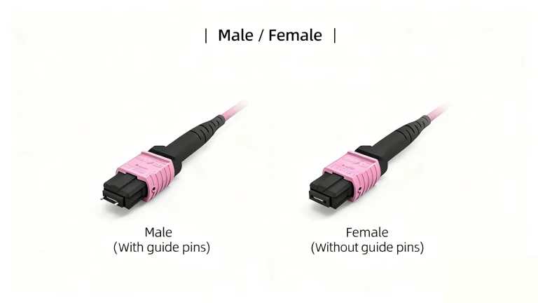
- Male: Features two guide pins protruding from the ferrule.
- Female: Features holes to accept the guide pins.Mating Rule: A male connector must always mate with a female connector (via an adapter or a transceiver port) to achieve the micro-precise physical alignment required for all fibers to connect simultaneously.
Polarity Methods (Types A, B, and C)
The Telecommunications Industry Association (TIA) defines three primary methods for managing polarity:
- Type A (Straight-Through): Uses a straight map from Fiber 1 to Fiber 1. Often used for patching links that require a patch cord reversal.
- Type B (Flipped/Reversed): Fiber 1 maps to Fiber 12. Most commonly connects two parallel optics transceivers directly (e.g., QSFP+ to QSFP+) because it provides the necessary end-to-end signal reversal.
- Type C (Pair Flipped): Flips each adjacent pair of fibers. Used in specialty applications where specific channel reversal is needed.
Very Small Form Factor MPOs and High-Speed Standards
Very Small Form Factor (VSFF) MPOs
New VSFF connectors, like the SN and CS, address extreme density needs at the patch panel. These connectors allow the high-fiber output of MPO trunk cables to fan out into smaller components, often half the size of LC, effectively doubling the density at the distribution frame. VSFF connectors enable tighter spacing in network equipment, reducing the overall footprint of the distribution layer.
MPO Applications and Insertion Loss
MPO enables high-speed data transmission through parallel optics, but this architecture demands high-quality connectors. Insertion loss (IL) is the main threat; every connection reduces the network’s power budget. High-speed transceivers require Ultra Low Insertion Loss (ULIL) performance, often below 0.35dB per connector. Poorly terminated MPOs introduce two other issues:
- High Insertion Loss: Reduces the signal strength, potentially breaking the link.
- Poor Return Loss (RL): Indicates reflections back to the transmitter, which disrupts laser stability and signal quality.
Only factory termination can guarantee the necessary IL and RL performance required for complex, high-bandwidth links.
Cleaning, Inspecting, and How to Test MPO Cable
Reliability hinges on clean, well-tested components. Because MPO connectors handle multiple fibers in a small area, contamination or damage to just one fiber can compromise the entire link.
How to Clean and Inspect MPOs
MPO connectors are highly sensitive to contamination. Always perform an inspection using a specialized multi-fiber microscope before insertion. Inspect the entire end-face array to check for microscopic particles. If needed, use specialized MPO cleaning tools (cassette cleaners) to wipe the entire fiber array simultaneously, ensuring you do not simply move contaminants from one fiber to another.
How to Test MPO Cable
You must use multi-fiber testing equipment (not single-strand power meters). Testing MPO cables requires two tiers of verification:
- Tier 1 Testing (Loss and Polarity): Use a high-end Optical Loss Test Set (OLTS) to simultaneously test the loss across all fibers, verifying ULIL performance against the power budget. Crucially, the test set must also perform a polarity check, confirming that the fiber mapping (Type A, B, or C) aligns correctly end-to-end.
- Tier 2 Testing (OTDR): Use an Optical Time Domain Reflectometer (OTDR) to characterize individual fiber lengths, attenuation, and splice quality within the trunk cable assembly, offering a detailed picture of the cable’s internal integrity.
PHILISUN’s Certified Cabling
PHILISUN provides specialty, factory-terminated MPO/MTP solutions for high-density applications. We offer MPO Trunk Cables, MPO Harnesses, and MPO Cassettes, all designed to meet the rigorous density and speed demands of modern data centers and ensure simple integration.
Every single PHILISUN MPO assembly undergoes rigorous factory testing for correct polarity (Type A, B, or C) and guaranteed Ultra Low Insertion Loss (ULIL). This meticulous component testing maximizes your network’s power budget and guarantees seamless integration from day one.
Conclusion
The MPO Connector makes high-speed networking possible, solving the density and cable management issues of traditional cabling. However, complexity surrounding polarity and the stringent need for ULIL performance make high-quality, pre-tested cabling a strategic necessity.
Choose PHILISUN for MPO solutions. We guarantee compatibility, correct polarity, and the low insertion loss required for mission-critical infrastructure. Select a quality you trust and protect your 100G and 400G investments.
Frequently Asked Questions (FAQ)
Q1: What is the main difference between MPO and MTP?
- A: MPO is the generic standard. MTP is a brand name for a mechanically enhanced MPO connector with superior stability.
Q2: Which MPO Polarity Type is standard for 100G?
- A: Type B is standard for connecting two parallel optics transceivers directly.
Q3: Can I clean MPO connectors myself?
- A: Yes, but only with specialized MPO cleaning tools.
Q4: Does MPO support both fiber types?
- A: Yes, MPO technology works with both Multimode and Single-mode fiber.