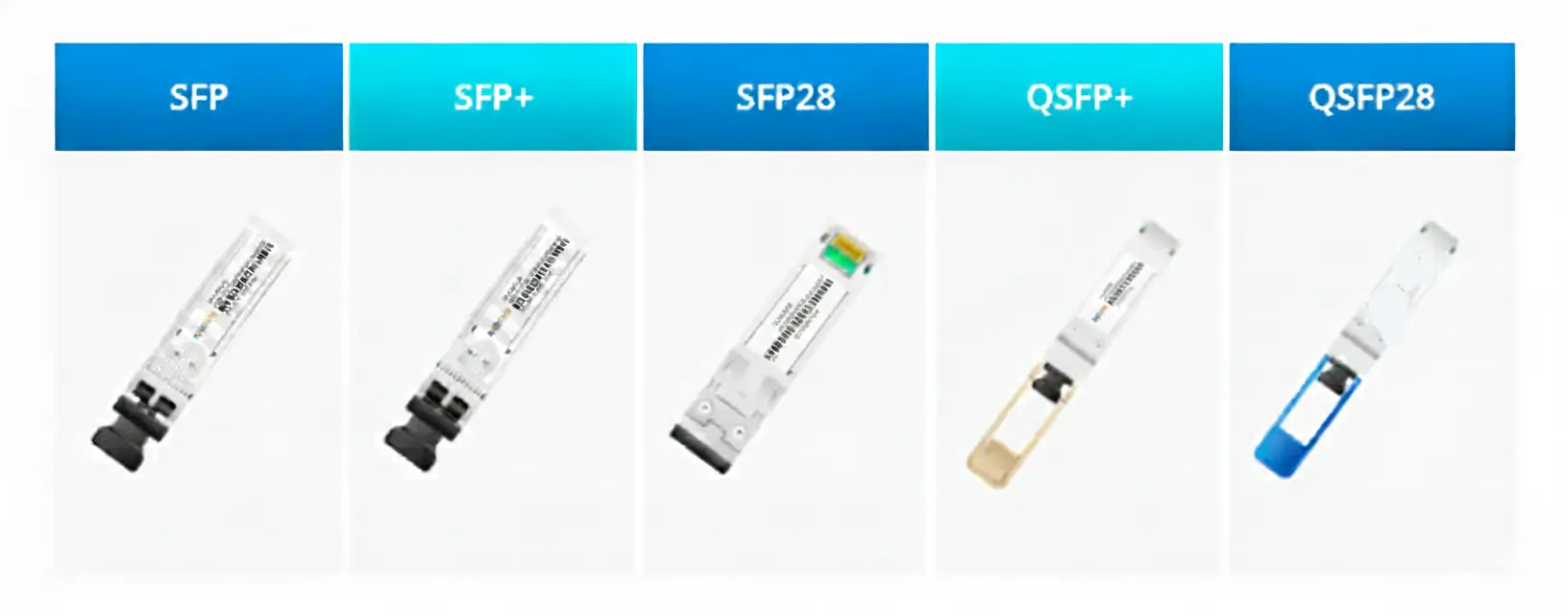

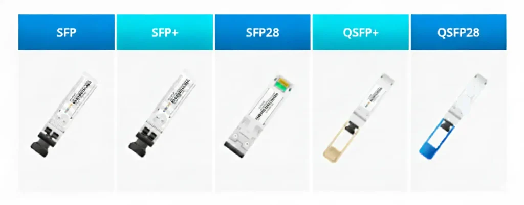
SFP and QSFP are different pluggable form-factor families: SFP uses one high-speed lane, while QSFP uses four. In a qsfp vs sfp decision, first match the host cage, then choose the supported rate, media, reach and connector. Typical Ethernet families are SFP at 1G, SFP+ at 10G, SFP28 at 25G, QSFP+ at 40G and QSFP28 at 100G.
QSFP vs SFP Selection Matrix
| Family / port label | Electrical lanes | Common Ethernet rate | Typical connector or cable | Breakout | Common use |
|---|---|---|---|---|---|
| SFP | 1 | 1G | Duplex LC, BiDi simplex LC, RJ45 | Not typical | Access and management links |
| SFP+ | 1 | 10G | Duplex LC, DAC, AOC | Endpoint for 40G breakout | Server and switch uplinks |
| SFP28 | 1 | 25G | Duplex LC, DAC, AOC | Endpoint for 100G breakout | 25G server access |
| QSFP+ | 4 | 40G (4×10G) | MPO/MTP, duplex LC, DAC, AOC | 40G to 4×10G | 40G aggregation |
| QSFP28 | 4 | 100G (4×25G) | MPO/MTP, duplex LC, DAC, AOC | 100G to 4×25G | 100G leaf-spine |
Choose in Four Steps
- Read the host cage label: identify SFP, SFP+, SFP28, QSFP+ or QSFP28 and the device model.
- Confirm rate and lane mode: check the hardware manual, firmware and port configuration rather than relying on physical fit.
- Select media and reach: decide between multimode or single-mode optics, BiDi, DAC or AOC.
- Match connector and coding: verify LC or MPO/MTP, polarity, vendor coding, DOM and temperature.
Port/cage note: the cage is the host mechanical and electrical interface; the inserted transceiver or cable assembly supplies the link implementation. For port, combo-port and troubleshooting detail, see what an SFP port is and how to use it.
SFP vs SFP+
SFP commonly carries 1 Gigabit Ethernet, while SFP+ commonly carries 10 Gigabit Ethernet in the same general small form factor. Mechanical similarity does not prove link support. Using an SFP module in an SFP+ cage is platform-dependent: the host must support that module, rate and port configuration.
SFP+ vs SFP28
SFP+ is normally a 10G single-lane interface; SFP28 is normally a 25G single-lane interface with tighter signal-integrity requirements. An SFP+ module may physically enter an SFP28 cage, but 10G fallback is platform-dependent. Confirm the switch/NIC matrix, firmware and configured rate.
SFP vs QSFP
SFP-family modules use one electrical lane; QSFP-family modules use four and provide greater faceplate density at aggregate rates. They are different mechanical form factors and are not directly interchangeable. Choose SFP for a native single-lane port or endpoint, and QSFP for a native quad-lane port, aggregation link or supported breakout.
QSFP+ vs QSFP28
QSFP+ commonly aggregates four 10G lanes for 40G; QSFP28 commonly aggregates four 25G lanes for 100G. Running a QSFP+ module at 40G in a QSFP28 cage is platform-dependent. Mechanical fit does not prove electrical or firmware support, so verify the exact cage mode and vendor documentation.
Compatibility Matrix
| Module and host cage | Mechanical fit | Operating result |
|---|---|---|
| SFP in SFP+ cage | Often yes | Platform-dependent; host must support 1G module and rate. |
| SFP+ in SFP28 cage | Often yes | Platform-dependent; host must support 10G fallback. |
| QSFP+ in QSFP28 cage | Often yes | Platform-dependent; host must expose a supported 40G mode. |
| SFP-family module in QSFP cage | No direct fit | Use an approved breakout cable/module path where supported. |
40G and 100G Breakout Decisions
40G to 4×10G maps four 10G lanes in a QSFP+ host port to four SFP+ endpoints. 100G to 4×25G maps four 25G lanes in a QSFP28 host port to four SFP28 endpoints. Both require supported host breakout mode, correct logical port mapping and compatible optics or cable assemblies.
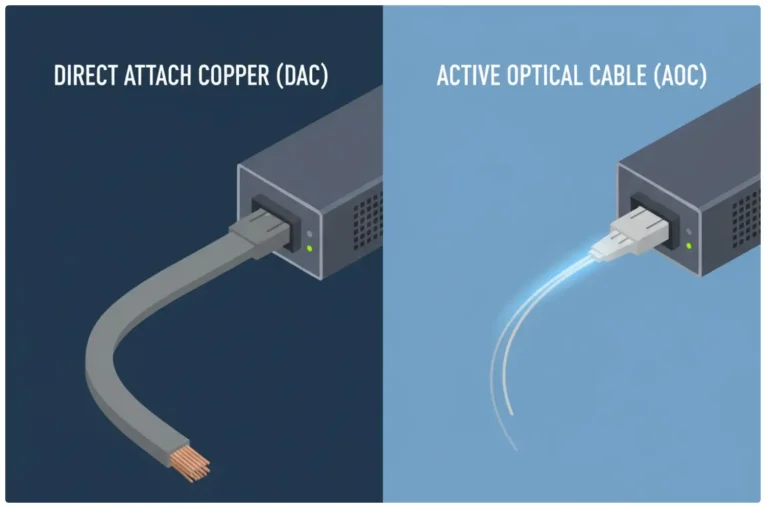
- DAC: short, fixed-length copper breakout for supported adjacent equipment.
- AOC: integrated optical breakout when a longer, lighter cable is useful.
- MPO/MTP optics: parallel optical lanes fan out through the correct fiber harness and polarity method.
Power and Thermal Planning
Power is module-specific, not determined by the cage name alone. Reach, laser technology, DSP functions, copper PHYs and operating-temperature grade can change power and heat within the same form factor. Compare the module maximum power with the host thermal budget, per-port power class, airflow direction and supported ambient temperature before deploying dense SFP28 or QSFP rows.
Reach Planning
| Example Ethernet optic | Nominal standards-based reach | Deployment condition |
|---|---|---|
| 10GBASE-SR | Up to 300 m on OM3 or 400 m on OM4 | Confirm modal bandwidth, connector loss and the exact optic data sheet. |
| 10GBASE-LR | 10 km on single-mode fiber | Check receiver limits and attenuation on short or patched links. |
| 25GBASE-SR | Up to 70 m on OM3 or 100 m on OM4 | Confirm FEC and host requirements for the chosen module. |
| 25GBASE-LR | 10 km on single-mode fiber | Validate the host, FEC mode and link budget. |
| 100GBASE-SR4 | Up to 70 m on OM3 or 100 m on OM4 | Requires the specified parallel-fiber path and polarity. |
| 100GBASE-LR4 | 10 km on single-mode fiber | Uses wavelength multiplexing over duplex LC; verify the full link budget. |
Connector and Reach Options
| Optical design | Common connector | Selection condition |
|---|---|---|
| SR / SR4 | Duplex LC for single-lane SR; MPO/MTP for parallel SR4 | Use the specified multimode fiber type and standard reach. |
| LR / LR4 | Duplex LC | Single-mode reach depends on the exact Ethernet standard and optic. |
| CWDM4 | Duplex LC | Four wavelengths share a duplex single-mode pair. |
| BiDi | Duplex LC or simplex LC, depending on design | Use the exact complementary wavelength pair and fiber plan. |
SFP and QSFP FAQ
Can an SFP module work in an SFP+ port?
Sometimes. The module may fit mechanically, but the host hardware, firmware and port configuration must explicitly support the module and lower rate. Check the platform compatibility matrix.
Can QSFP28 ports run QSFP+ modules at 40G?
Some platforms support 40G operation in selected QSFP28 cages, while others do not. The result is platform-dependent and may require a port-mode or firmware setting.
Does every QSFP module use an MPO connector?
No. Parallel SR4 and breakout optics often use MPO/MTP, but LR4, CWDM4 and some BiDi designs can use duplex LC. Select the connector from the exact module specification.
When should I use a breakout cable?
Use breakout when the host supports lane splitting and you need four lower-speed endpoints, such as 40G to 4×10G or 100G to 4×25G. Confirm host breakout mode, port mapping and the correct DAC, AOC or MPO path.
Choose the Right SFP or QSFP Family
Compare PHILISUN optical transceivers, 1G SFP, 10G SFP+, 25G SFP28, 40G QSFP+, 100G QSFP28, AOC and DAC options. Contact PHILISUN with the host model, port label, speed, reach, fiber/connector, temperature and coding requirement for a compatibility recommendation.