Scaling networks to 100G and 400G requires the high-density solution of the Multi-fiber Push-On (MPO) cable. Yet, MPO technology’s complexity—involving crucial decisions on polarity, gender, and fiber count—often leads to expensive deployment errors. This definitive guide cuts through that confusion by detailing the MPO’s anatomy and breaking down Polarity Types A, B, and C, ensuring you have the technical knowledge for a flawless, error-free high-speed network deployment.
MPO Foundational Anatomy and Standards
The MPO connector is governed by the international IEC 61754-7 standard and represents a feat of high-precision engineering. Understanding its physical components is critical for deployment and maintenance.
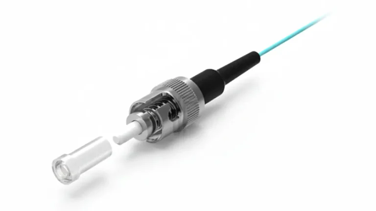
The MT Ferrule: Heart of the MPO Connector
The core of the MPO is the MT (Mechanical Transfer) Ferrule. Unlike the ceramic ferrules of LC or SC connectors, the MT ferrule is typically made from a high-precision polymer composite. This composite material allows the simultaneous molding of a complex array of holes designed to house the optical fibers in a precise, high-tolerance linear array. The dimensional accuracy of the ferrule pitch is paramount, as any misalignment severely degrades performance. The ferrule tip is polished (either PC for Multimode or APC for Single-Mode) to minimize back reflection and ensure optimal physical contact.
Mating Features: Keying and Gender (Pins)
MPO functionality depends entirely on correct physical mating, enforced by two features:
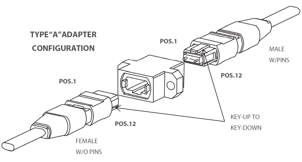
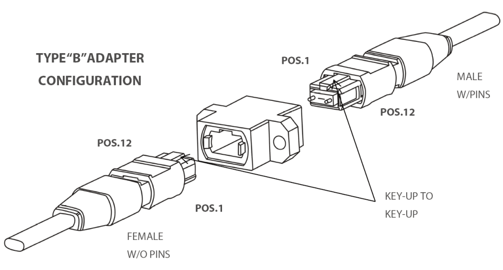
- Keying: The connector body features a key that dictates the orientation of the ferrule (Key-Up or Key-Down). This key is essential for managing polarity across the entire network link, ensuring the fiber mapping remains consistent from end-to-end.
- Gender: MPO connectors use guide pins to achieve the necessary precise alignment for optimal mating. Connectors are designated as male (pinned) or female (unpinned). A proper connection requires a male connector to mate with a female connector. Attempting to mate two male connectors can bend the pins and damage the ferrules, while two female connectors will misalign the fibers, causing catastrophic insertion loss.
Governing Standards and MTP Distinction
In North America, the EIA/TIA 604-5 (FOCIS 5) standard defines the physical requirements for the MPO interface. While MPO is the generic standard, the MTP connector (a registered trademark of US Conec) is a high-performance MPO variant. MTP connectors offer mechanical enhancements such as elliptical guide pins, metal pin clamps, and floating ferrules, ensuring they consistently exceed the generic MPO standard for mechanical durability and low loss.
Critical Technical Functionality: Polarity Management
Polarity management is the most complex aspect of MPO deployment. In parallel optics, ensuring the Transmit (Tx) signal on the equipment connects correctly to the Receive (Rx) port on the corresponding equipment is vital.
The Tx-to-Rx Challenge in Parallel Optics
The TIA-568-C.3 standard defines two primary Polarity Methods (Method A and Method B) that guide the deployment strategy. The specific MPO cable assembly type used determines how the fibers are mapped, and thus how the link achieves polarity.
MPO Cable Polarity Types: A, B, and C Breakdown
The MPO cable itself comes in three distinct fiber mapping types:
| Polarity Type | Fiber Mapping | Key Orientation | Primary Use Case |
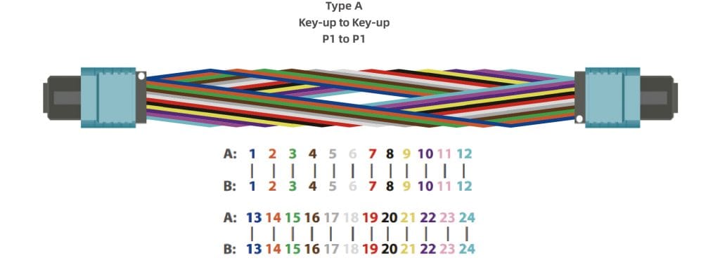
| Type A (Straight-Through) | Fiber 1 (Tx) connects to Fiber 1 (Rx). | Key-Up to Key-Down | Patch panel/cassette trunking links. |
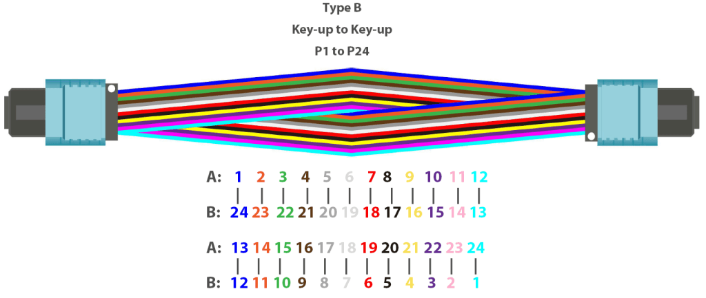
| Type B (Crossed/Rollover) | Fiber 1 (Tx) connects to Fiber 12 (Rx), Fiber 2 to Fiber 11, etc. | Key-Up to Key-Up | Direct transceiver-to-transceiver links (e.g., 100G QSFP to QSFP). |
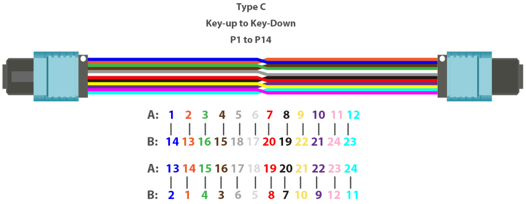
| Type C (Pair-Flipped) | Pairs 1/2 are flipped on the far end (F1 to F2, F2 to F1). | Key-Up to Key-Down | Specific legacy parallel applications. |
We often use Type B in 40G/100G transceiver links because the transceiver itself often performs a flip, simplifying the overall channel.
Practical Polarity Management
The complexity of MPO mapping necessitates the use of auxiliary components to convert the MPO trunk signal into usable duplex ports. MPO Cassettes are modules that house the conversion internally, presenting the end-user with standard LC or SC ports that are polarity-correct. Being specialized assemblies, MPO Harnesses (Breakout Cables) allow a single MPO port to fan out to multiple LC or SC connectors, and maintain the correct Tx/Rx pairing at the termination point.
- PHILISUN provides MPO cables in all three Polarity Types (A, B, and C) and offers specialized guidance to customers to ensure the correct configuration based on their transceiver model and chosen deployment method.
MPO’s Essential Role in High-Speed Data Center Migration
The density and speed supported by MPO technology are indispensable for scaling modern network architectures.
40G/100G Breakout and Aggregation
The MPO breakout application is one of its most common uses. It allows a single high-speed port to be broken out into multiple lower-speed channels, utilizing the concept of parallel optics:
- A 40G QSFP+ port (using 4 Tx / 4 Rx lanes) can be connected via a 12-fiber MPO cable that breaks out into four separate 10G LC duplex connections.
- Similarly, a 100G QSFP28 port can be broken out into four 25G SFP28 links.
Trunking for 400G and 800G
MPO is the backbone technology for current and future speeds. New standards necessitate higher fiber counts:
- 400GBASE-SR8 utilizes 16-fiber MPO (8 Tx / 8 Rx lanes).
- 400GBASE-DR4 utilizes 8-fiber MPO for single-mode, long-reach applications.
MPO Trunk Cables are used to build the high-density backbone link between distribution areas (e.g., MDA to HDA), providing a scalable foundation ready for any speed upgrade simply by swapping out transceivers and patch cords.
- PHILISUN specializes in manufacturing these pre-terminated MPO trunk cables, helping data centers achieve up to a 70% reduction in cable volume compared to using traditional individual patch cords.
Single-Mode MPO for Long-Reach Links
While MPO is often associated with multimode short-reach applications, single-mode MPO (distinguished by its APC, Angled Physical Contact, polish) is critical for long-distance, high-speed campus and distributed data center connections, notably in standards like 400G-DR4.
Installation, Testing, and Quality Assurance Best Practices
In B2B environments, the value of MPO lies not just in its speed but in its reliability. Proper installation and certification are non-negotiable.
MPO Cleaning and Inspection
Fiber end-face contamination is the number one cause of network failure. Because MPO ferrules contain 8 to 24 fibers, contamination on one ferrule can simultaneously degrade multiple channels. Therefore, specialized MPO cleaning tools and automated fiber inspection scopes must be used to inspect every mating connection before deployment.
Tier 1 and Tier 2 Certification
Certification is essential for verifying performance:
- Tier 1 Certification (Insertion Loss): This fundamental test verifies that the total power loss of the MPO link (including the connector loss) is within the budget, typically performed with a Light Source and Power Meter.
- Tier 2 Certification (OTDR): This test maps the physical characteristics of the link, verifying the integrity of splices and link components. Specialized MPO test reference cords are required for both certifications.
Customization and Procurement Reliability
Successful deployment requires customized components—specific cable lengths, jacket fire ratings (Plenum or LSZH), and specialized Polarity configurations. Sourcing these from a reliable supplier is crucial. Working with a certified manufacturer like PHILISUN ensures factory-tested MPO assemblies, compliant with all TIA/IEC standards, and provided with traceable test reports, minimizing deployment risks.
Conclusion
The MPO cable is the fundamental architectural enabler for high-density, high-speed parallel optics. Its unique plug-and-play structure drastically cuts installation time, while its multi-fiber design maximizes the utilization of precious rack space and simplifies migration paths from 10G to 400G and beyond. Understanding the key components and required Polarity Type is essential, making the MPO cable an indispensable standard for the modern enterprise network.
Ready to simplify your high-density cabling and ensure flawless polarity? Contact the PHILISUN engineering team to design and order your factory-tested MPO cable assemblies today.
FAQ
- Q1: What is the most common MPO fiber count used today?
- The 12-fiber MPO is historically the most common, but the 8-fiber and 16-fiber MPOs are rapidly gaining ground for 40G/100G/400G deployments, as they optimize fiber usage.
- Q2: Can I use MPO for single-mode fiber?
- Yes. MPO/MTP connectors are used for both multimode (OM3/OM4) and single-mode (OS2) fiber, with single-mode versions always requiring an Angled Physical Contact (APC) polish.
- Q3: What does the white dot on an MPO connector mean?
- The white dot denotes the first fiber position (Position 1) in the array. This marker is critical for ensuring correct polarity alignment during installation.