

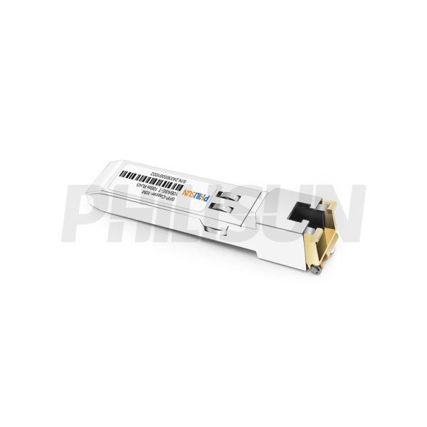
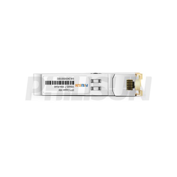
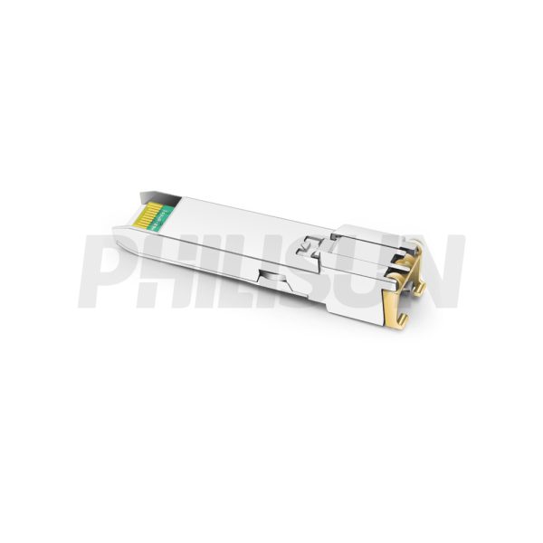
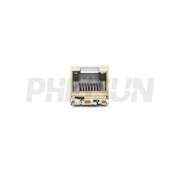


Generic Compatible 10GBASE-T SFP 100m Copper RJ45 Transceiver Module
SFPCO-001A-01-RJ45-SGMII
- High Quality
- Factory Outlet
- Satisfaction Guarantee
- Global Shipping
| SPECIFICATIONS | |||
|---|---|---|---|
| Product Model | SFPCO-001A-01-RJ45-SGMII | Manufacturer Brand | PHILISUN |
| Package Type | SFP | Optical Connector | RJ45 |
| Max Data Rate | 125Mbps | 10G Effective Transmission Distance | 100m |
| Hot-Pluggable SFP | YES | Operating voltage | 3.3V |
| Power Consumption | - | Protocols | SFP MSA IEEE Std 802.3 |
| Operating Temperature(Commercial) | 0℃~+70℃ | Storage Temperature(Commercial) | -40℃~+85℃ |
| Operating Temperature(Industrial) | -40℃~+85℃ | Storage Temperature(Industrial) | -40℃~+85℃ |
| Absolute Maximum Ratings | |||||||||
| Parameter | Symbol | Min. | Typ | Max. | |||||
| Maximum supply voltage | Vcc | -0.5 | – | 4.0 | |||||
| Storage temperature | TS | -40 | – | +85 | |||||
| Normal Operating Condition | |||||||||
| Parameter | Symbol | Min | Typ | Max | Units | Ref. | |||
| Operating case temperature | Tc | 0 | – | 70 | °C | Standard | |||
| -40 | – | 85 | Industrial | ||||||
| Supply voltage | Vcc | 3.15 | 3.3 | 3.45 | V | – | |||
| Electrical Characteristics | |||||||||
| Parameter | Symbol | Min | Typ | Max | Units | Notes/Conditions | |||
| +3.3 Volt Electrical Power Interface | |||||||||
| Supply current | Icc | – | 170 | 300 | mA | – | |||
| Input voltage | Vcc | 3.13 | 3.3 | 3.47 | V | – | |||
| Surge vurrent | Isurge | – | – | 30 | mA | – | |||
| Low-Speed Signals, Electronic Characteristics | |||||||||
| SFP output low | VOL | 0 | – | 0.5 | V | 4.7k to 10k pull-up to host_Vcc,measured at host side of connector | |||
| SFP output high | VOH | host_Vcc-0.5 | – | host_Vcc+0.3 | V | 4.7k to 10k pull-up to host_Vcc, measured at host side of connector | |||
| SFP input low | VIL | 0 | – | 0.8 | V | 4.7k to 10k pull-up to Vcc, measured at SFP side of connector | |||
| SFP input high | VIH | 2 | – | Vcc + 0.3 | V | 4.7k to 10k pull-up to Vcc, measured at SFP side of connector | |||
| High-Speed Electrical Interface, Transmission Line-SFP | |||||||||
| Line baud rates | fL | – | 125 | – | MHz | MLT-3 encoding per IEEE802.3u | |||
| TX output impedance | Zout, TX |
–
|
100 | – | Ohm | Differential, AC coupled Internally | |||
| RX input impedance | Zin, RX | – | 100 | – | Ohm | Differential, AC coupled Internally | |||
| High-Speed Electrical Interface, Host-SFP | |||||||||
| Single ended data input swing | Vin | 250 |
–
|
1200 | mV | Single ended | |||
| Single ended data output swing | Vout | 300 | – | 1000 | mV | Single ended | |||
| Rise/Fall time | Tr, Tf |
–
|
3 |
–
|
nsec | 20%-80% | |||
| TX Iinput impedance | Zin |
–
|
50 |
–
|
Ohm | Single ended | |||
| RX output impedance | Zout | – | 50 | – | Ohm | Single ended | |||
| General Specifications | |||||||||
| Parameter | Symbol | Min | Typ | Max | Units | Notes/Conditions | |||
| Data rate | SFPCO-001A-01-RJ45-SGMII | – | 10 | – | Mbps | – | |||
| Distance | – | – | – | 100 | m | Category 5 UTP. BER <10-12 | |||
| Pin No. | Name | Function | Plug Seq. | Notes | |||||
| 1 | VeeT | Transmitter ground | 1 | – | |||||
| 2 | TX fault | Transmitter fault indication | 3 | 1 | |||||
| 3 | TX disable | Transmitter disable | 3 | 2 | |||||
| 4 | MOD-DEF2 | Module definition 2 | 3 | 3 | |||||
| 5 | MOD-DEF1 | Module definition 1 | 3 | 3 | |||||
| 6 | MOD-DEF0 | Module definition 0 | 3 | 3 | |||||
| 7 | Rate select | Not connected | 3 | – | |||||
| 8 | LOS | Los of signal | 3 | 4 | |||||
| 9 | VeeR | Receiver ground | 1 | – | |||||
| 10 | VeeR | Receiver ground | 1 | – | |||||
| 11 | VeeR | Receiver ground | 1 | – | |||||
| 12 | RD- | Inv. received data out | 3 | 5 | |||||
| 13 | RD+ | Received data out | 3 | 5 | |||||
| 14 | VeeR | Receiver ground | 1 | – | |||||
| 15 | VccR | Receiver power | 2 | 6 | |||||
| 16 | VccT | Transmitter power | 2 | 6 | |||||
| 17 | VeeT | Transmitter ground | 1 | – | |||||
| 18 | TD+ | Transmit data in | 3 | 7 | |||||
| 19 | TD- | Inv. transmit data in | 3 | 7 | |||||
| 20 | VeeT | Transmitter ground | 1 | – | |||||
| 1. TX Fault is not used and tied to ground within the module.
2. TX Disable is not used and is not connected within the module. 3. MOD-DEF 0,1,2 are the module definition pins. They should be pulled up with a 4.7k~10kΩ resistor on the host board. The pull-up voltage shall be VccT or VccR. 4. The LOS will be LVTTL low for link ok and will be LVTTL high for link off. Externally pull up to VccR or VccT with 4.7k – 10k ohm on host board. 5. These are the differential receiver output. Internally AC-coupled in the transceiver. 100Ω differential lines and 100 Ω terminate resistor should be used on the host board. 6. VccT and VccR are internally connected together in the transceiver. 7. These are the differential receiver input. Internally AC-coupled in the transceiver. 100Ω differential lines and 100 Ω terminate resistor is used in the transceiver. |
|||||||||

These SFP use a 128 byte EEPROM with an address of A0H.
| Table 1 Serial ID Memory Contents | |||||||||
| Addr. | Size(Bytes) | Name of Field | Hex | Description | |||||
| BASE ID FIELDS | |||||||||
| 0 | 1 | Identifier | 03 | SFP | |||||
| 1 | 1 | Ext. Identifier | 04 | SFP function is defined by serial ID only | |||||
| 2 | 1 | Connector | 22 | RJ-45 | |||||
| 3- 10 | 8 | Transceiver | 00 00 00 20 00 00 00 00 | 100BASE-FX | |||||
| 11 | 1 | Encoding | 02 | 4B5B | |||||
| 12 | 1 | BR, Nominal | 01 | 100M | |||||
| 13 | 1 | Reserved | 00 | – | |||||
| 14 | 1 | Length (9µm)km | 00 | Transceiver transmit distance |
|||||
| 15 | 1 | Length(9µm)100m | 00 | ||||||
| 16 | 1 | Length (50µm) 10m | 00 | ||||||
| 17 | 1 | Length(62.5µm)10m | 00 | ||||||
| 18 | 1 | Length (Copper) | 64 | 100m | |||||
| 19 | 1 | Reserved | 00 | – | |||||
| 20-35 | 16 | Vendor name | XX XX XX XX XX XX XX XX 20 20 20 20 20 20 20 20 | Vendor name (ASCII) | |||||
| 36 | 1 | Reserved | 00 | – | |||||
| 37-39 | 3 | Vendor OUI | XX XX XX | – | |||||
| 40-55 | 16 | Vendor PN | Transceiver part number | ||||||
| 56-59 | 4 | Vendor rev | XX XX XX XX | – | |||||
| 60-61 | 2 | Wavelength | 00 | – | |||||
| 62 | 1 | Reserved | 00 | – | |||||
| 63 | 1 | CC_BASE | Check Sum (Variable) | Check code for Base ID Fields | |||||
| EXTENDED ID FIELDS | |||||||||
| 64-65 | 2 | Options | 00 00 | – | |||||
| 66 | 1 | BR,max | 00 | – | |||||
| 67 | 1 | BR,min | 00 | – | |||||
| 68-83 | 16 | Vendor SN | XX XX XX XX XX XX XX XX 20 20 20 20 20 20 20 20 | Serial Number of transceiver (ASCII). For example“B000822” . | |||||
| 84-91 | 8 | Date code | XX XX XX XX XX XX XX XX | Manufacture date code. For example “080405” . | |||||
| 92-94 | 3 | Reserved | XX | – | |||||
| 95 | 1 | CC_EXT | Check Sum (Variable) | Check sum for Extended ID Field. | |||||
| VENDOR SPECIFIC ID FIELDS | |||||||||
| 96-127 | 32 | Vendor Specific | Read only | Depends on customer information | |||||
| 128-255 | 128 | Reserved | Read only | – | |||||

Related products
-

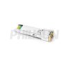
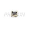
Generic Compatible 10/100BASE-T SFP 100m Copper RJ45 Transceiver Module
SFPCO-01A-01-RJ45-SGMII
-

Generic Compatible 10/100/1000BASE-T SFP 100m Copper RJ45 Transceiver Module
SFPCO-1A-01-RJ45-SGMII