
Quick answer: POTN network architecture combines packet switching and optical transport. Optical modules and fiber cabling sit at the physical layer of that architecture, connecting access, aggregation, metro and data center nodes with the right speed, reach, wavelength, connector and link budget.
A basic POTN definition explains why Packet Optical Transport Network technology merges packet services with optical transmission. This guide takes the next step: where the optical modules, fiber cabling, patching and high-speed interconnects fit when a carrier, enterprise or data center team plans a POTN upgrade.
POTN Architecture Overview
A POTN system usually combines packet processing, switching, transport, management and optical interfaces in one transport platform. The packet layer handles Ethernet and service flows. The transport layer provides the optical path. The physical layer is where the network depends on transceivers, fiber type, connectors, patch panels and cable routes.
| POTN layer | Main role | Physical-layer decision |
|---|---|---|
| Access | Collect enterprise, mobile or edge traffic | SFP, SFP+ or SFP28 reach, fiber type and connector format |
| Aggregation | Combine multiple packet services | 10G, 25G, 40G or 100G port planning and patching density |
| Metro transport | Move services between sites or rings | Single-mode fiber, wavelength plan and optical power budget |
| Data center or DCI edge | Connect cloud, storage and switching layers | 100G/400G optics, MPO or LC cabling and upgrade headroom |
Where Optical Modules and WDM Fit in POTN
Optical modules convert the electrical interface of the POTN equipment into an optical signal for the fiber route. In practical projects, the module choice is driven by speed, distance, fiber type, wavelength, connector, power budget and equipment compatibility. PHILISUN optical transceivers support common SFP, SFP+, SFP28, QSFP+, QSFP28, QSFP-DD and OSFP planning paths.
| Port or upgrade stage | Common module family | Typical POTN use |
|---|---|---|
| Access and low-rate service ports | SFP or SFP+ | Ethernet service access, mobile backhaul edge and short metro links |
| 40G aggregation | QSFP+ 40G series | Aggregation uplinks and intermediate transport upgrades |
| 100G metro or DCI edge | QSFP28 100G series | High-capacity aggregation, DCI edge and backbone-facing interfaces |
| 400G growth path | QSFP-DD 400G series | High-density transport, cloud interconnect and future capacity expansion |
Fiber Cabling and Patching Considerations
The fiber layer determines whether the selected optics can actually perform as planned. A POTN upgrade should document fiber type, route length, connector interface, patch-panel path, insertion loss, return loss, bend radius and labeling before modules are purchased in volume.
- Fiber type: single-mode fiber is the normal choice for metro, long-reach and backbone POTN routes.
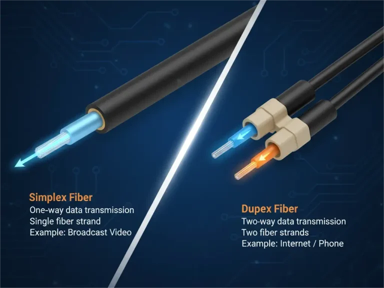
- Connector format: LC is common for many duplex optical modules, while MPO may appear in high-density or parallel optics environments.
- Link budget: route length, splice loss, connector loss and patch-panel loss must fit the module specification.
- Serviceability: clear labeling and documented patch routes reduce troubleshooting time during maintenance.
- Upgrade path: leave room for higher-speed optics and denser cabling if the network may move from 40G to 100G or 400G.
For projects that need a complete physical-layer plan, PHILISUN fiber optic network and cabling solutions can combine transceivers, patch cords, high-density cabling and route recommendations around the equipment interface.
Common POTN Upgrade Scenarios
| Scenario | What changes | What to confirm |
|---|---|---|
| PTN to POTN migration | Packet services move onto a stronger optical transport layer | Existing fiber quality, service interface and module compatibility |
| Metro capacity expansion | Aggregation or ring capacity increases from 10G/40G toward 100G | Reach, wavelength, connector loss and spare fiber availability |
| Enterprise or campus interconnect | Multiple sites need stable optical transport and packet services | Fiber route documentation, transceiver speed and protection design |
| Data center edge upgrade | POTN connects cloud, storage or backbone-facing interfaces | 100G or 400G optics, cabling density and future expansion room |
How to Choose Modules by Reach and Interface
Start with the equipment port, then match the module to the actual fiber route. Do not choose optics only by data rate. Two 100G modules can have very different reach, wavelength, connector and power-budget requirements.
- Confirm the port form factor, such as SFP+, SFP28, QSFP+, QSFP28, QSFP-DD or OSFP.
- Confirm target speed and service mapping, such as 10G, 25G, 40G, 100G or 400G.
- Measure the routed fiber distance, including patch panels and service loops.
- Check fiber type, connector type and available fiber count.
- Review the optical budget against expected insertion loss.
- Confirm platform coding, DOM/DDM requirements and vendor compatibility.
- Keep spare modules and documented patching for fast field replacement.
PHILISUN Product Path for POTN Projects
For POTN upgrades, send your equipment model, port interface, target speed, reach, fiber type, connector path and quantity. PHILISUN can help select compatible optical modules and cabling for access, aggregation, metro and data center transport links.
Useful starting points include optical transceivers for module selection, fiber optic network solutions for cabling architecture, and contacting PHILISUN when the project requires compatibility checks or custom reach planning.
POTN Architecture FAQ
What is POTN network architecture?
POTN network architecture combines packet switching with optical transport. It is used when networks need Ethernet service flexibility and high-capacity optical transmission in the same transport platform.
Where do optical modules fit in POTN?
Optical modules sit at the physical interface of the POTN equipment. They define the optical signal speed, reach, wavelength, connector and fiber compatibility for each link.
Which fiber is used for POTN networks?
Single-mode fiber is commonly used for POTN metro, backbone and DCI routes because it supports longer distance and higher-capacity optical transmission. The exact fiber path still needs loss and connector checks.
Can POTN use 100G or 400G optical modules?
Yes. POTN platforms may use 100G or 400G optical modules when the equipment port, service mapping, reach and fiber route support those speeds. Compatibility and link budget should be checked before deployment.
What information is needed for a POTN module recommendation?
Provide the equipment model, port form factor, target speed, required reach, fiber type, connector path, link budget if available, quantity and any vendor compatibility requirements.