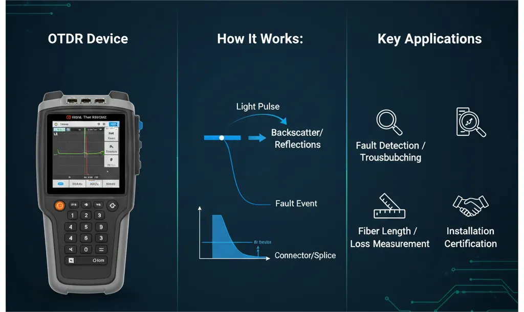
OTDR testing uses an Optical Time Domain Reflectometer to send light pulses into a fiber link and read the returned backscatter and reflection. The result is an OTDR trace: a distance-based map that shows fiber length, splice loss, connector loss, reflectance, bends, breaks and the end of the fiber.
Use an OTDR when you need to locate a fault, document a new cable route, compare a link against a baseline, or understand where loss occurs inside a fiber path. For total end-to-end insertion loss certification, use an OLTS or light source and power meter as well. OTDR and OLTS tests answer different questions, so mature fiber acceptance testing often uses both.
OTDR Testing Quick Answer
An OTDR test tells you where loss or reflection happens inside a fiber link. Clean the connectors, connect a launch cable, set the correct wavelength, range, pulse width and index of refraction, run the trace, then review events such as connectors, splices, bends and fiber end. For acceptance work, save the trace as a baseline and compare it with the link budget and OLTS insertion loss result.
What Is an OTDR?
An OTDR, or Optical Time Domain Reflectometer, is a fiber optic test instrument that works like a radar for optical cable. It launches a short pulse of light into the fiber and measures the light that returns over time. Because time can be converted into distance, the OTDR can show where events occur along the cable.
The returned light comes mainly from two effects. Rayleigh backscatter creates the sloping baseline that shows fiber attenuation. Fresnel reflection creates sharp peaks at reflective points such as connectors, mechanical splices, open ends or fiber breaks.
OTDR vs OLTS: Which Test Should You Use?
| Question | OTDR | OLTS / power meter |
| What does it measure? | Event location, event loss, reflectance, fiber length and trace shape | Total end-to-end insertion loss |
| Best use | Troubleshooting, route mapping, fault location and Tier 2 documentation | Acceptance testing and pass/fail loss certification |
| Main output | Distance-based trace and event table | Total loss value in dB |
| Weakness | Can misread close events, launch/receive ends or gainers if setup is poor | Does not show where the loss occurs |
| Practical answer | Use OTDR to find and document events | Use OLTS to confirm total channel loss |
For a deeper comparison, read OLTS vs OTDR: A Complete Guide.
OTDR Testing Procedure: Step-by-Step Checklist
| Step | Action | Why it matters |
| 1 | Inspect and clean connectors | Dirty connectors create false loss and reflection events |
| 2 | Confirm fiber type and test wavelength | Single-mode and multimode links require different settings and expectations |
| 3 | Connect a launch cable | Moves the first connector outside the OTDR dead zone |
| 4 | Connect a receive cable when testing the full link | Allows the last connector to be measured before the trace ends |
| 5 | Set range, pulse width, averaging time and IOR | These settings control resolution, distance accuracy and dynamic range |
| 6 | Run the test at required wavelengths | Common wavelengths include 850/1300 nm for multimode and 1310/1550 nm for single-mode |
| 7 | Review the trace and event table | Identify connectors, splices, bends, breaks and unexpected reflections |
| 8 | Save baseline traces and notes | Creates documentation for warranty, maintenance and future fault comparison |
Before testing, review the cable assembly type. A short data center link may use fiber patch cords and pigtails, while high-density routes may use MPO cable assemblies, MPO trunk cables or MPO cassettes.
How to Read an OTDR Trace
An OTDR trace plots returned optical power against distance. The sloping line shows fiber attenuation, while steps and peaks show events. The event table is useful, but the trace shape should still be reviewed manually because automatic event detection can miss close events, gainers or poor launch conditions.
| Trace event | What it looks like | Likely meaning | Action |
| Connector pair | Reflective peak followed by a loss step | Mated connector, adapter or patch panel point | Check cleanliness, mating quality and reflectance |
| Fusion splice | Small non-reflective loss step | Permanent splice point | Compare splice loss against project limit |
| Macrobend | Loss that is stronger at longer wavelength | Bend radius issue or stress point | Inspect routing and bend management |
| Fiber break | Large reflection and trace end before expected distance | Open fiber, cut, severe damage or disconnected end | Locate by distance and inspect the route |
| Gainer | Event appears to have negative loss | Backscatter mismatch between two fiber sections | Use bidirectional averaging |
| Noise floor | Trace becomes unstable at far distance | Signal too weak near instrument limit | Increase averaging or adjust pulse width/range |
Trace interpretation is closely related to insertion loss and return loss. If a connector creates both high loss and high reflection, cleaning or replacement is often required.
Launch Cable, Receive Cable and Dead Zones
A launch cable sits between the OTDR and the fiber under test. It allows the instrument output reflection to settle before the first connector of the link appears on the trace. A receive cable sits at the far end and allows the last connector to be measured. Without these cables, the first and last connectors can hide inside dead zones.
| Term | Meaning | Why it matters |
| Event dead zone | Minimum distance needed to separate two reflective events | Short patching fields may hide close connectors |
| Attenuation dead zone | Distance needed after a reflection before loss can be measured accurately | Important for first connectors and closely spaced events |
| Launch cable | Known cable before the link under test | Measures the first connector and stabilizes the trace |
| Receive cable | Known cable after the link under test | Measures the last connector and confirms end loss |
OTDR Settings: Parameters That Change the Result
| Parameter | What to set | Trade-off |
| Wavelength | Match fiber type and project requirement | Longer wavelengths reveal bend issues more clearly |
| Range | Set just beyond expected link length | Too long wastes resolution; too short cuts off the end |
| Pulse width | Short for short links, longer for long links | Short pulse improves resolution; long pulse improves dynamic range |
| Averaging time | Increase for cleaner traces | Longer averaging improves signal-to-noise but takes more time |
| IOR / group index | Use the fiber manufacturer or project value | Wrong IOR shifts event distance |
| Event thresholds | Match project acceptance limits | Too strict creates noise; too loose misses real events |
Common OTDR Testing Mistakes
- Testing dirty connectors: Always inspect and clean before connecting the OTDR. See the PHILISUN guide to cleaning fiber optic connectors.
- No launch cable: The first connector may be hidden in the OTDR dead zone.
- No receive cable: The final connector cannot be measured correctly.
- Wrong pulse width: A long pulse on a short data center link can merge nearby events.
- Wrong IOR: Event distance can be inaccurate, making field fault location harder.
- Relying only on one direction: Bidirectional testing helps resolve gainers and backscatter mismatch.
When Should You Use OTDR Testing?
OTDR testing is useful when installing a new backbone, troubleshooting unexpected loss, documenting a long route, proving splice quality, locating a break, checking high-density MPO cabling, or creating a baseline before network handover. It is especially valuable for campus, telecom, data center and industrial links where the physical route is long or difficult to inspect.
For design work, combine OTDR traces with the fiber type, link budget, connector count and module specification. PHILISUN supports these projects with factory-tested fiber assemblies, MPO cabling, patch panels and optical transceivers that can be matched to the target link distance and loss budget.
OTDR Testing FAQ
What does OTDR stand for?
OTDR stands for Optical Time Domain Reflectometer. It sends light pulses into a fiber and measures returned backscatter and reflection to create a distance-based trace of the link.
What is OTDR testing used for?
OTDR testing is used to locate fiber faults, measure fiber length, identify connectors and splices, estimate event loss and reflectance, find bends or breaks, and document fiber routes for maintenance or acceptance testing.
Do I need a launch cable for OTDR testing?
Yes, a launch cable is recommended because it moves the first connector of the link outside the OTDR dead zone. A receive cable is also useful when the last connector needs to be measured.
Can an OTDR measure total insertion loss?
An OTDR can estimate event and link loss from the trace, but an OLTS or light source and power meter is normally the preferred tool for total end-to-end insertion loss certification.
Why do OTDR traces sometimes show negative loss?
Negative loss, often called a gainer, can appear when two fiber sections have different backscatter characteristics. Bidirectional OTDR testing and averaging are used to calculate a more accurate event loss.
Conclusion
OTDR testing gives technicians a map of what is happening inside a fiber link. The strongest results come from clean connectors, proper launch and receive cables, correct OTDR settings, careful trace interpretation and good baseline documentation.
For factory-tested fiber jumpers, MPO assemblies, patching hardware or help matching link budget to cable and transceiver selection, contact PHILISUN.