Structured cabling is the planned, documented cabling system that connects work areas, network rooms, equipment rooms and data center racks through a repeatable physical infrastructure. In a fiber-heavy network, it usually includes backbone fiber, MPO trunks, LC patching, fiber enclosures, cassettes, labeling, pathways and test records.
Good structured cabling is not just a neat rack. It gives the network a physical layer that can support new switches, faster optical transceivers, cleaner troubleshooting and lower-risk upgrades without rebuilding the cable plant every time the topology changes.

Structured Cabling Quick Answer
Structured cabling is a standards-based approach to building network cabling from stable zones: entrance facility, equipment room, backbone cabling, telecommunications rooms, horizontal cabling and work area connections. For modern data centers and enterprise networks, the fiber portion often uses OS2, OM3, OM4 or OM5 cabling, MPO trunks, LC patch cords, cassettes and patch panels to create a scalable, testable physical layer.
What Structured Cabling Includes
A structured cabling system divides the physical network into areas that can be designed, labeled and maintained consistently. The names vary by project, but the functions below are common in enterprise LAN and data center cabling plans.
| Area | Purpose | Fiber cabling example |
| Entrance facility | Where service-provider, campus or building links enter the site | OS2 backbone cable, splice tray, outdoor-to-indoor transition |
| Equipment room or MDA | Main network equipment, core switches and major cross-connects | MPO trunk termination, LC patch panel, high-density fiber enclosure |
| Backbone cabling | Links between rooms, floors, buildings or data center zones | OS2, OM4 or OM5 fiber backbone with documented loss budget |
| Telecommunications room or IDF | Intermediate distribution and access switching point | Fiber patch panel, cassette, LC jumpers and switch uplinks |
| Horizontal cabling | Cabling from the distribution room to work areas or access points | Copper for users, fiber for high-bandwidth endpoints or long runs |
| Work area or equipment edge | Device-side connection point | LC patch cord, duplex adapter, equipment jumper or transceiver port |
For product selection, PHILISUN’s fiber optic network solutions page is a useful starting point. For the cabling layer itself, see MPO cable assemblies, fiber patch cords and pigtails and optical transceivers.
Fiber Backbone Design in Structured Cabling
The backbone is the part of structured cabling that most directly affects upgrade capacity. It connects core rooms, distribution rooms, rows, cabinets or buildings. Because it is harder to replace than short patch cords, it should be planned for the next speed step, not only today’s switch ports.
| Design choice | Common option | When it fits |
| Singlemode backbone | OS2 fiber with LC or MPO terminations | Longer campus links, future high-speed optics, lower distance risk |
| Multimode backbone | OM3, OM4 or OM5 fiber | Shorter data center and building links using SR optics |
| Connector strategy | MPO in backbone, LC at equipment edge | High-density cabling with clean breakout or cassette management |
| Spare fiber count | Extra fibers in trunks or backbone cables | Growth, redundancy and easier moves/adds/changes |
| Loss budget | Documented connector, splice and fiber attenuation allowance | Every optical link, especially 40G, 100G, 400G and longer reach |
If you are comparing fiber grades, use the PHILISUN multimode fiber guide and single-mode vs multimode fiber comparison before locking the cabling plan.
MPO in Data Center Structured Cabling
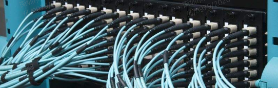
MPO cabling is common in high-density structured cabling because it carries multiple fibers in one connector. A typical design uses factory-terminated MPO trunks in the backbone, then transitions to LC or smaller MPO links near equipment. This reduces field termination work and makes large cabling projects easier to document.
| MPO product | Role in structured cabling | Useful PHILISUN page |
| MPO trunk cable | Main high-density backbone between panels, rooms or rows | MPO trunk cable |
| MPO harness cable | Breaks one MPO into multiple duplex links at equipment or panel side | MPO harness cable |
| MPO breakout cable | Connects parallel optics or splits fiber groups for planned port layouts | MPO breakout cable |
| MPO cassette | Converts MPO backbone into managed LC patching positions | MPO cassette |
| MPO fiber enclosure | Houses cassettes, adapters, trunks and patching hardware | MPO fiber enclosure |
| MPO jumper | Short equipment or panel connection where MPO-to-MPO is required | MPO jumper |
For deeper MPO planning, read the complete MPO cabling guide, MPO trunk vs harness vs breakout cable and MPO fiber count guide.
Copper vs Fiber in Structured Cabling
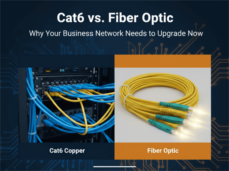
Most enterprise structured cabling systems use both copper and fiber. Copper is practical for short access connections, PoE endpoints and many office work areas. Fiber is usually the better fit for backbone, high-speed uplinks, long distance, high density and EMI-sensitive locations.
| Requirement | Copper cabling | Fiber cabling |
| Short desktop links | Very practical, especially with PoE | Used when bandwidth, distance or isolation requires it |
| Backbone links | Limited by distance and speed | Preferred for building, campus and data center backbone |
| High rack density | Bulkier cable bundles | MPO and LC designs save pathway and panel space |
| Electrical noise | More sensitive to EMI | Immune to electromagnetic interference |
| Future speed upgrades | May require new category cabling | Often easier to upgrade by changing optics and patching design |
Structured Cabling Planning Checklist
Before purchasing cable assemblies, define the physical and optical requirements. A clean bill of materials normally comes from the answers below.
- Topology: Identify core, distribution and equipment-edge connection points.
- Speed roadmap: Plan for current and next-step optics, such as 10G, 25G, 40G, 100G or 400G.
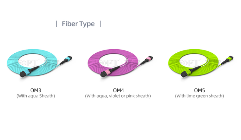
- Fiber type: Choose OS2, OM3, OM4 or OM5 based on distance, transceiver type and upgrade plan.
- Connector format: Decide where to use MPO, LC, cassettes, harnesses and adapter panels.
- Polarity: Document MPO polarity, pin/gender, fiber count and end-to-end mapping before ordering.
- Loss budget: Count connectors, cassettes, splices and cable length before selecting optical modules.
- Pathway: Confirm bend radius, tray fill, separation, fire rating and cable management space.
- Labeling: Use a consistent label format for rack, panel, port, cable ID and far-end destination.
- Testing: Define insertion loss, polarity and OTDR documentation requirements before installation starts.
If the cabling system will support many transceiver types, also review LC vs SC vs MPO connectors, insertion loss vs return loss and SFP port selection.
Testing and Documentation
Structured cabling should be tested as a system, not only as loose cable. For fiber links, acceptance testing normally includes connector inspection, polarity verification, insertion loss testing and trace documentation where needed. For long backbone routes or fault location, OTDR testing creates a distance-based record of events.
| Test or document | What it proves | Why it matters |
| Visual inspection and cleaning | Connector end faces are clean and undamaged | Prevents avoidable loss and reflection |
| Polarity test | Transmit and receive paths are mapped correctly | Critical for MPO trunks, cassettes and duplex links |
| Insertion loss test | Total end-to-end optical loss | Confirms the link can support the selected transceiver |
| OTDR trace | Event location, length, reflections and abnormal bends | Useful for backbone documentation and troubleshooting |
| As-built record | Rack, panel, port, cable ID, fiber type and test result | Makes future changes faster and safer |
For field testing details, use the PHILISUN OTDR testing guide and fiber jacket and connector color code guide.
Common Structured Cabling Mistakes
- Designing only for today’s ports: Backbone cabling should leave room for speed upgrades, redundancy and added racks.
- Ignoring MPO polarity: MPO trunks, cassettes and breakout cables must be mapped as one system.
- Mixing fiber types without documentation: OS2, OM3, OM4 and OM5 should be clearly labeled and separated in records.
- Overfilling pathways: Crowded trays and poor bend management can create hidden attenuation problems.
- Skipping test records: Without baseline loss and trace data, troubleshooting after handover becomes much slower.
PHILISUN Structured Cabling Product Path
A practical PHILISUN fiber structured cabling path usually starts with the network architecture, then selects backbone trunks, patching hardware and device-side optics as one matched system.
| Need | Recommended starting point |
| Data center or enterprise fiber architecture | Fiber optic network solutions |
| High-density backbone cabling | MPO trunk cable |
| Transition from MPO backbone to LC equipment ports | MPO cassette or MPO harness cable |
| Rack patching and moves/adds/changes | Fiber patch cords and pigtails |
| Switch or server optical interface | Optical transceivers |
Structured Cabling FAQ
What is structured cabling?
Structured cabling is a planned network cabling system that organizes cables, rooms, racks, patch panels, pathways, labels and test records into a repeatable physical infrastructure.
What are the main parts of a structured cabling system?
The main parts normally include the entrance facility, equipment room, backbone cabling, telecommunications room, horizontal cabling and work area connections.
Is fiber better than copper for structured cabling?
Fiber is usually better for backbone, long distance, high-speed uplinks and high-density data center cabling. Copper is still practical for short access links, desktop connections and PoE devices.
Where are MPO trunks used in structured cabling?
MPO trunks are commonly used in high-density backbone links between fiber panels, rows, cabinets or network rooms. They can later break out to LC ports through cassettes or harness cables.
How should structured cabling be tested?
Structured cabling should be tested with connector inspection, polarity checks, insertion loss testing and, when needed, OTDR trace documentation. The results should be stored with the cable ID and as-built records.
Conclusion
Structured cabling gives the network a stable physical layer. For fiber projects, the strongest result comes from a documented backbone design, correct fiber type, planned MPO-to-LC transition, clean patching hardware and complete test records.
For help matching fiber backbone, MPO cabling, patch panels and optical transceivers to a new data center or enterprise network project, contact PHILISUN.