

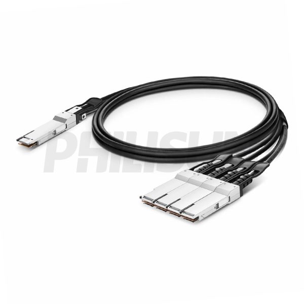
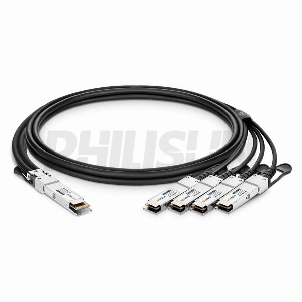
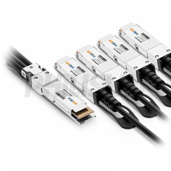
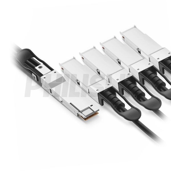
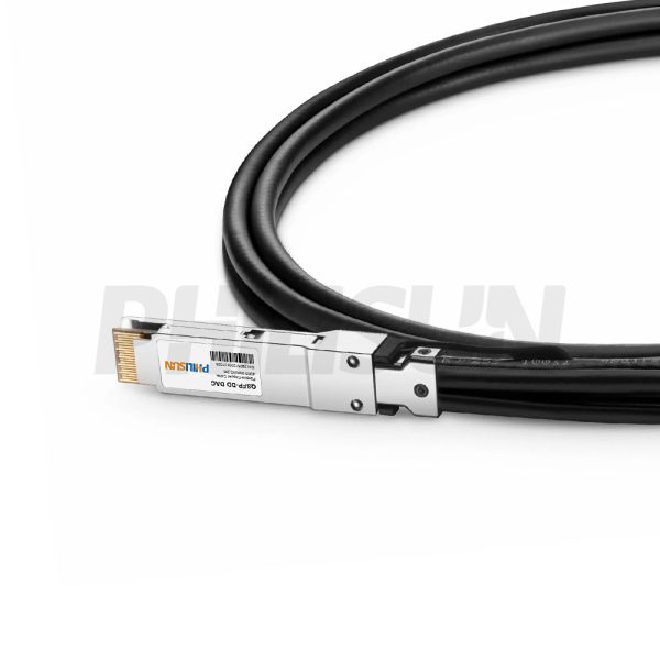
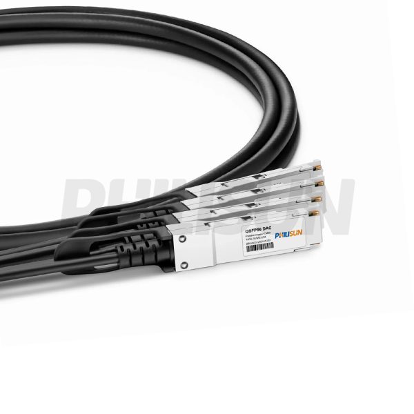
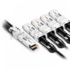
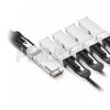

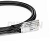
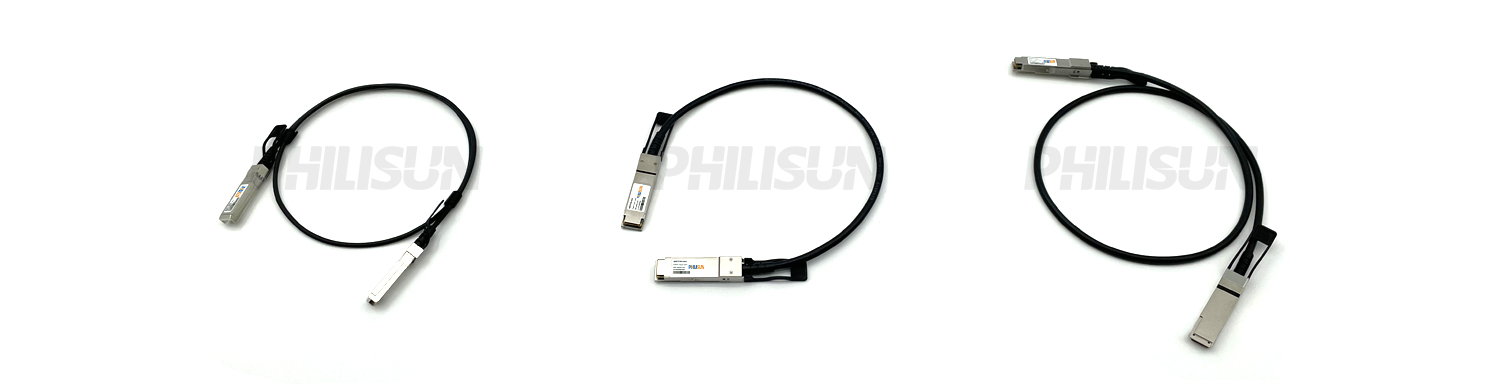
400G QSFP-DD to 4×100G QSFP56 Passive Direct Attach Copper Twinax Cable (DAC)
Compliant with SFF-8665、QSFP-DD MSA、IEEE802.3bj、IEEE802.3cd standard
Switch to Switch
Switch to GPU
- High Quality
- Factory Outlet
- Satisfaction Guarantee
- Global Shipping
| SPECIFICATIONS | |||
|---|---|---|---|
| Cable End Connector A | QSFP-DD | Cable End Connector B | 4×QSFP56 |
| Jumper Type | Active Optical Breakout Cable | Data Rate | 400G |
| Aggregate Bit Rate | 400Gbps | Lane Bit Rate | 50Gbps |
| Number of Channels | 8 | Single Channel Rate | 50G |
| Minimum Bend Radius | 5X Cable OD -Single, 10X Cable OD - Repeated | Factory Brand | PHILISUN |
| Attenuation | 28AWG:10dB/7m maximum 30AWG:8.4dB/5.5m maximum | Bit Error Rate | ≤10-12 |
| Shield | Braid/Foil | Wire AWG | 28AWG/30AWG |
| Cable Type | Passive Twinax | Cable OD | 30AWG: 7.0mm 28AWG: 8.2mm |
| Cable Colour/Material | Black PVC(OFNR) | Cable Length Selection | 0.5-3meter |
| Protocols | SFF 8665/QSFP-DD MSA/QSFP56 MSA/SFF8436/CMIS Rev 4.0/IEEE 802.3cd/IEEE802.3bj/SFF8679/ | Application Scenarios | 400Gigabit Ethernet (400GbE) |
| Supply Voltage | 3.3V | Power Dissipation | <0.1W |
| Operating Temperature | 0 to 70℃ (32 to 158℉) | Storage Temperature | -40 to 85℃ (-40 to 185℉) |
PRODUCT PRESENTATION
The PHILISUN 400G QSFP-DD to 4x100G QSFP56 Passive Direct Attach Copper Twinax Cable (DAC) provides a powerful High-Density Breakout solution, splitting a 400G QSFP-DD port into four independent 100G QSFP56 links. Compliant with the QSFP-DD MSA, IEEE 802.3bj, and IEEE 802.3cd standard, this Passive Copper DAC Cable ensures stable and reliable performance. It delivers Ultra-Low Latency for short-reach Server Interconnects and is the most Cost-Effective way to connect Switch to Switch fabrics and accelerate data paths from Switch to GPU nodes in HPC environments.
DAC SERIES PRODUCTS
PRODUCTION & TESTING EQUIPMENT

Pin connection
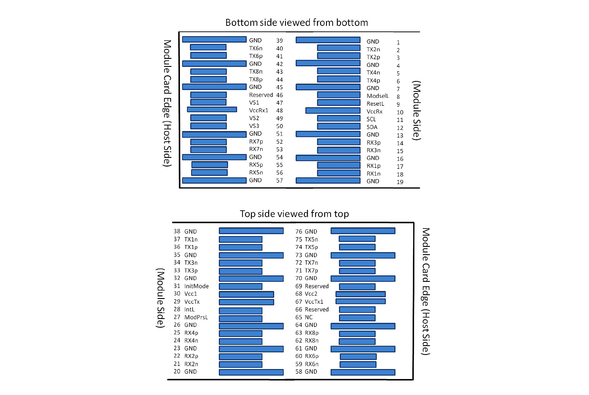
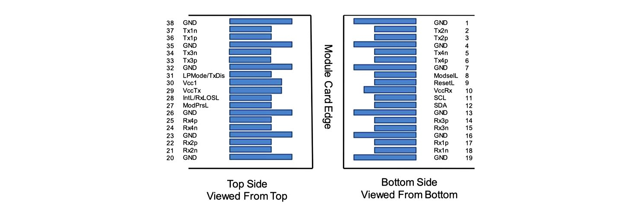
| Pin No. | P1 (QSFP-DD) | P2 (QSFP) | |||||||
| Pin | Signal | Pin | Signal | ||||||
| 1 | 18 | RX1n | 37 | TX1n(QSFP-1) | |||||
| 17 | RX1p | 36 | TX1p(QSFP-1) | ||||||
| 2 | 36 | TX1p | 17 | RX1p(QSFP-1) | |||||
| 37 | TX1n | 18 | RX1n(QSFP-1) | ||||||
| 3 | 21 | RX2n | 2 | TX2n(QSFP-1) | |||||
| 22 | RX2p | 3 | TX2p(QSFP-1) | ||||||
| 4 | 3 | TX2p | 22 | RX2p(QSFP-1) | |||||
| 2 | TX2n | 21 | RX2n(QSFP-1) | ||||||
| 5 | 15 | RX3n | 37 | TX1n(QSFP-2) | |||||
| 14 | RX3p | 36 | TX1p(QSFP-2) | ||||||
| 6 | 33 | TX3p | 17 | RX1p(QSFP-2) | |||||
| 34 | TX3n | 18 | RX1n(QSFP-2) | ||||||
| 7 | 24 | RX4n | 2 | TX2n(QSFP-2) | |||||
| 25 | RX4p | 3 | TX2p(QSFP-2) | ||||||
| 8 | 6 | TX4p | 22 | RX2p(QSFP-2) | |||||
| 5 | TX4n | 21 | RX2n(QSFP-2) | ||||||
| 9 | 56 | RX5n | 37 | TX1n(QSFP-3) | |||||
| 55 | RX5p | 36 | TX1p(QSFP-3) | ||||||
| 10 | 74 | TX5p | 17 | RX1p(QSFP-3) | |||||
| 75 | TX5n | 18 | RX1n(QSFP-3) | ||||||
| 11 | 59 | RX6n | 2 | TX2n(QSFP-3) | |||||
| 60 | RX6p | 3 | TX2p(QSFP-3) | ||||||
| 12 | 41 | TX6p | 22 | RX2p(QSFP-3) | |||||
| 40 | TX6n | 21 | RX2n(QSFP-3) | ||||||
| 13 | 53 | RX7n | 37 | TX1n(QSFP-4) | |||||
| 50 | RX7p | 36 | TX1p(QSFP-4) | ||||||
| 14 | 71 | TX7p | 17 | RX1p(QSFP-4) | |||||
| 72 | TX7n | 18 | RX1n(QSFP-4) | ||||||
| 15 | 62 | RX8n | 2 | TX2n(QSFP-4) | |||||
| 63 | RX8p | 3 | TX2p(QSFP-4) | ||||||
| 16 | 44 | TX8p | 22 | RX2p(QSFP-4) | |||||
| 43 | TX8n | 21 | RX2n(QSFP-4) | ||||||
Electrical Performance Requirements
| Test Items | Test Condition | Specification | |||||||
| Current | – | 0.5A per Contact | |||||||
| Voltage | – | 30 vDC per Contact | |||||||
| LLCR | EIA 364-23, 20mVdc, 100mA | Less Than 2 ohms. | |||||||
| Insulation Resistance |
100 Vdc | 10 Mohms Minimum between Adjacent Contacts | |||||||
| Dielectric Withstanding Voltage |
300 VDC Minimum for 1 Minutes | No Defect or Breakdown between Adjacent Contacts | |||||||
| Temperature Rise | Measure the Temperature Rise at the Rated Current after 96 hours(45 minutes ON/15 minutes OFF per hour). |
Temperature Rise: +30℃ MAX. | |||||||
| Continuity | Verify the Continuous Electrical Path | No Open, Short, or High Resistance. | |||||||
SI Requirements
| Test Items | Specification | Notes | |||||||
| SDD21&SDD12 | -17.16 dB Min. @13.28 GHz | From 0.01 GHz- 19GHz | |||||||
| SDD11&SDD22 | -16.5+2*sqrt(f)dB Max. @0.05GHz~4.1GHz -10.66+14*log(f/5.5)dB Max.@4.1GHz~10GHz |
From 0.01 GHz- 19GHz | |||||||
| SCD21-SDD21 | -10 dB Max. @0.01 GHz~12.89 GHz-27+(29/22)*f dB Max. @12.89 GHz~15.7 GHz -6.3 dB Max. @15.7 GHz~19 GHz |
From 0.01 GHz- 19GHz | |||||||
Pin Function Definitions
| Test Items | Test Condition | Specification | |||||||
| Mating Forces | A rate of 10mm per minute | QSFP-DD<90N, QSFP<60N | |||||||
| Un-mating Forces | A rate of 10mm per minute | QSFP-DD<50N,QSFP<30N | |||||||
| Latch strength | Pull to separate module from cage , Test with connector, cage & module (latch engaged) |
Minimum of an 125N force | |||||||
| Bulk cable retention in module | Pull to separate bulk cable from module,Test with cable assembly only | Minimum of an 90N force | |||||||
| Wire Flex |
Flex cable 180 for 10 cycles at X/Y axis, 20 times/minutes, with an 1kg suspended weight. Type C EIA 364-41, test condition I.
|
No microsecond discontinuities are allowed. | |||||||
| Durability | Perform 50 unplug/plug cycles | No evidence of physical damage | |||||||
| Cable Minimum Bend Radius | The cable is bent on time over the correct mandrel with 5 perpendicular, the Minimum bend Radius is 10x OD. | 1.No physical damage 2.Verify continuity and SI |
|||||||
PRODUCT CERTIFICATION

COMPATIBLE BRANDS

CONFIGURATION INFORMATION
Related products
-

400G QSFP-DD to 8×50G SFP56 Passive Direct Attach Copper Twinax Cable (DAC)
Compliant with QSFP-DD MSA、SFF-8432、IEEE 802.3bs-400GAUI-8、IEEE802.3cd-50GAUI-1、CMIS 4.0、SFF-8472 standard
Switch to Switch
Switch to GPU -

400G QSFP-DD to QSFP-DD Passive Direct Attach Copper Twinax Cable (DAC)
Compliant with IEEE 802.3cd, QSFP-DD MSA, CMIS 4.0 standard
Switch to Switch
Switch to GPU -

400G QSFP-DD to 2×200G QSFP56 Passive Direct Attach Copper Twinax Cable (DAC)
Compliant with SFF-8679、QSFP-DD MSA、IEEE802.3bj、IEEE802.3cd standard
Switch to Switch
Switch to GPU