

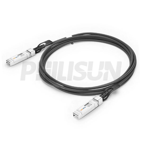
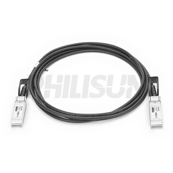
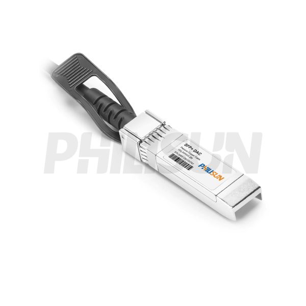
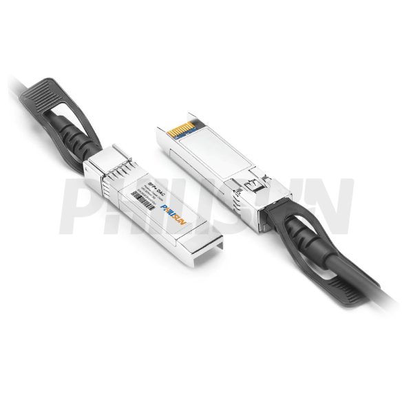
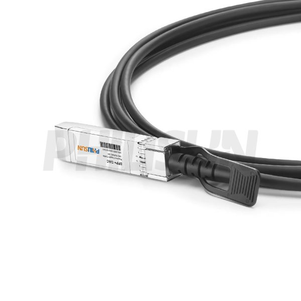
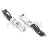
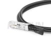
10G SFP+ to SFP+ Passive Direct Attach Copper Twinax Cable (DAC)
Compliant with IEEE 802.3、SFF-8431、QSFP28 MSA standard
Switch to Switch
Switch to GPU
- High Quality
- Factory Outlet
- Satisfaction Guarantee
- Global Shipping
| SPECIFICATIONS | |||
|---|---|---|---|
| Cable End Connector A | SFP+ | Cable End Connector B | SFP+ |
| Jumper Type | Direct-Attach | Data Rate | 10G |
| Aggregate Bit Rate | 10.5Gbps | Lane Bit Rate | 10.5Gbps |
| Number of Channels | 1 | Single Channel Rate | 10G |
| Minimum Bend Radius | 5X Cable OD | Factory Brand | PHILISUN |
| Attenuation | 24AWG:10dB/10m maximum 30AWG:8.4dB/5.5m maximum | Bit Error Rate | ≤10-12 |
| Shield | Braid/Foil | Wire AWG | 26AWG/30AWG |
| Cable Type | Passive Twinax | Cable OD | 30AWG: 4.2mm 24AWG: 6.0mm |
| Cable Colour/Material | Black PVC(OFNR) | Cable Length Selection | 0.5-10 meter |
| Protocols | IEEE 802.3/SFF-8431/SFP+ MSA 1x InfiniBand QDR, DDR, SDR | Application Scenarios | 10Gigabit Ethernet (10GbE) |
| Supply Voltage | 3.3V | Power Dissipation | <0.5W |
| Operating Temperature | 0 to 70℃ (32 to 158℉) | Storage Temperature | -40 to 85℃ (-40 to 185℉) |
PRODUCT PRESENTATION
The PHILISUN 10G SFP+ to SFP+ Passive Direct Attach Copper Cable (DAC) is a reliable, high-speed solution for short-reach 10 Gigabit Ethernet (10GbE) connectivity. It is compliant with the IEEE 802.3, SFF-8431, and QSFP28 MSA standard, ensuring compatibility and stability. This cost-effective, low-latency cable is essential for direct links from Switch to Switch and high-throughput connections from Switch to GPU within the same rack or adjacent racks.
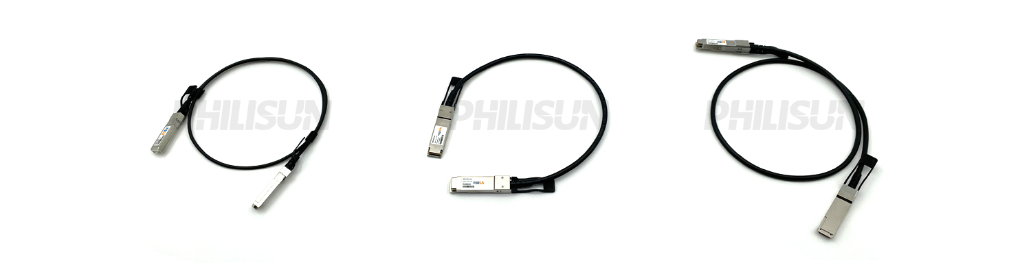
DAC SERIES PRODUCTS
PRODUCTION & TESTING EQUIPMENT

PERFORMANCE PARAMETER
| Absolute Maximum Ratings | |||||||||
| Parameter | Symbol | Min | Typ. | Max | Unit | ||||
| Operating Case Temperature | Tc | 0 | 25 | 70 | ℃ | ||||
| Relative Humidity | RH | 5 | – | 95 | % | ||||
| Supply Voltage | – | 3.15 | 3.3 | 3.45 | v | ||||
| Data Rate Per Lane | – | 1 | 10.5 | – | Gbp/s | ||||
| Performance Specification | |||||||||
| Electrical | |||||||||
| Min. Dielectric Withstand Voltage | 300 VDC | ||||||||
| Insulation Resistance | 1000 Mohms | ||||||||
| Current Rating | 0.5 Amp Min/Signal Contact | ||||||||
| General | |||||||||
| Operating Temperature | 0 to 70 ℃ | ||||||||
| Flammability Rating | UL 94 V-0 | ||||||||
| Green Features | RoHS, Lead-Free | ||||||||
| Shield | Braid/Foil | ||||||||
| Marking | Mfg Name, Part#, Date Code | ||||||||
| Plug | |||||||||
| Backshell Material | Nickel-Plated Zinc Diecast | ||||||||
| Contact Material | PCB with Gold-Plated Pads | ||||||||
| Latch | Positive Latching w/Pull | ||||||||
| Insertion Force | 30N Max | ||||||||
| Withdrawal Force | 20N Max | ||||||||
| Retention Force | 90N Max | ||||||||
| Durability | 50 Cycles Min | ||||||||
| Cable | |||||||||
| Conductor | Solid | ||||||||
| Wire Gauge | AWG30, AWG28, AWG26, AWG24 | ||||||||
| Impedance | 100± 5 ohms | ||||||||
| Cable OD | AWG 30 :4.2mm | ||||||||
| AWG 28 :4.7mm | |||||||||
| AWG 26:5.2mm | |||||||||
| AWG 24: 6.0mm | |||||||||
| Jacket Type | PVC | ||||||||
| Bend Radius | 5X Cable OD | ||||||||
| Electrical Characteristics | |||||||||
| Test Type | Test Item | 24AWG | 26AWG | 28AWG | 30AWG | ||||
| Electrical Characteristics |
Differential impedance |
100±5Ω @ TDR | 100±5Ω | 100±5Ω | 100±5Ω @ TDR | ||||
| Mutual capacitance | 14pF/ft nominal | 14pF/ft nominal | 14pF/ft nominal | 14pF/ft nominal | |||||
| Time delay | 1.31ns/ft nominal, (4.3ns/m) nominal | 1.35ns/ft nominal | 1.35ns/ft nominal | 1.35ns/ft nominal, (4.3ns/m) nominal |
|||||
| Time delay skew (within pairs) |
80ps/ 10m maximum | 120ps/8.5m maximum |
120ps/7m maximum |
50ps/5.5m maximum | |||||
| Time delay skew (between pairs) |
350ps/ 10m maximum | 500ps/8.5m maximum |
500ps/7m maximum |
350ps/5.5m maximum |
|||||
| Attenuation | 10dB/ 10m maximum @1.25Ghz | 10dB/8.5m maximum @1.25Ghz | 10dB/7m maximum @1.25Ghz | 8.4dB/5.5m maximum @ 1.25Ghz | |||||
| Conductor DC Resistance |
0.026Ω /ft maximum @20°C | 0.04Ω /ft maximum@ 20°C | 0.06Ω/ft maximum@20°C | 0.01Ω/ft maximum@20°C | |||||
| Physical Characteristics |
Conductors (two pair) | 24AWG Solid, Silver plated copper | 26AWG Solid, Silver plated copper | 28AWG Solid, Silver plated copper | 30AWG Solid, Silver plated copper | ||||
| Insulation | Foam polyolefin | Foam polyolefin | Foam polyolefin | Foam polyolefin | |||||
| Pair drain wire | 26AWG Solid, Silver plated copper | 28AWG Solid, Silver plated copper | 30AWG Solid, Silver plated copper | 30AWG Solid, Silver plated copper | |||||
| Overall cable shield | Aluminum/polyester tape, 125% coverage, Tin plated copper braid, 38AWG, 85% coverage | Aluminum/polyester tape, 125% coverage, Tin plated copper braid, 38AWG, 85% coverage | Aluminum/polyest er tape, 125% coverage,Tin plated copper braid, 38AWG, 85% coverage |
Aluminum/polyester tape, 125% coverage,Tin plated copper braid, 38AWG, 85% coverage |
|||||
| Outer diameter | 6.0mm | 5.2mm | 4.7mm | 4.2mm | |||||
| Pin Designation | |||||||||
| Pin | Logic | Symbol | Name/Description | Notes | |||||
| 1 | – | VeeT | Transmitter Ground | – | |||||
| 2 | LV-TTL-O | TX_Fault | N/A | 1 | |||||
| 3 | LV-TTL-I | TX_DIS | Transmitter Disable | – | |||||
| 4 | LV-TTL-I/O | SDA | Tow Wire Serial Data 5 LV | – | |||||
| 5 | LV-TTL-I | SCL | Tow Wire Serial Clock | – | |||||
| 6 | – | MOD_DEF0 | Module present, connect to VeeT | – | |||||
| 7 | LV-TTL-I | RS0 | N/A | 1 | |||||
| 8 | LV-TTL-O | LOS | LOS of Signal | – | |||||
| 9 | LV-TTL-I | RS1 | N/A | 1 | |||||
| 10 | – | VeeR | Receiver Ground | – | |||||
| 11 | – | VeeR | Receiver Ground | – | |||||
| 12 | CML-O | RD- | Receiver Data Inverted | – | |||||
| 13 | CML-O | RD+ | Receiver Data Non-Inverted | – | |||||
| 14 | – | VeeR | Receiver Ground | – | |||||
| 15 | – | VccR | Receiver Supply 3.3V | – | |||||
| 16 | – | VccT | Transmitter Supply 3.3V | – | |||||
| 17 | – | VeeT | Transmitter Ground | – | |||||
| 18 | CML-I | TD+ | Transmitter Data Non-Inverted | – | |||||
| 19 | CML-I | TD- | Transmitter Data Inverted | – | |||||
| 20 | – | VeeT | Transmitter Ground | – | |||||
PRODUCT CERTIFICATION

COMPATIBLE BRANDS

CONFIGURATION INFORMATION