QSFP112 is a four-lane QSFP-family pluggable form factor designed for 112G-class electrical signaling per lane, enabling 400G-class interconnects in a compact port. The name describes the host-side form factor and lane architecture. It does not, by itself, tell you the optical reach, fiber type, connector, protocol, FEC setting or whether a module is approved by a particular switch or NIC.
That distinction matters during a 400G upgrade. Two products can both carry a QSFP112 label yet use different optical interfaces, cables, management implementations and vendor coding. A reliable selection starts with the host port and application, then works outward to media, reach and platform validation.
QSFP112 in one minute
- QSFP means quad small form-factor pluggable: four high-speed host electrical lanes in a compact module family.
- 112 refers to the 112 Gb/s-class signaling target per electrical lane. It is not a promise of 112 Gb/s of application data on every lane.
- Four lanes provide the host-side architecture used for 400G-class links.
- The module type still matters: an optical transceiver, passive DAC or AOC solves a different distance and cabling problem.
- Compatibility is multi-layered: mechanical fit, electrical mode, protocol, management, coding, media and thermal conditions must all agree.
The QSFP112 MSA describes a module and cage/connector system based on the established QSFP family. This lets system designers preserve high front-panel density while moving a four-lane host interface toward 400G. It does not turn every older QSFP port into a QSFP112 port, and it does not make every 400G module interchangeable.
How the four-lane architecture works
A QSFP112 host interface has four transmit and four receive electrical lanes. Each lane operates in the 112G signaling class, commonly using PAM4 signaling. The aggregate architecture supports a 400G-class port after the system accounts for line coding, protocol overhead and FEC. For this reason, multiplying four by 112 and calling the result “448G usable bandwidth” is misleading.
The electrical lane count is also not the same as the optical lane count. Inside a transceiver, electrical signals may be retimed or converted into an optical interface defined for parallel fibers or multiple wavelengths. A 400G SR4 implementation, for example, solves a different link than a single-mode DR4 or FR4-class design. The relevant module specification determines fiber type, connector, wavelength plan and supported reach.
It also helps to separate baud rate, encoded bit rate and delivered network capacity. PAM4 carries two encoded bits per symbol, while FEC and protocol framing protect the link and consume part of the raw line rate. Switch software usually presents an operational port speed such as 400G rather than the sum of four nominal lane labels. For planning and troubleshooting, use the host’s supported interface mode and the module data sheet instead of reverse-engineering payload from the form-factor name.
QSFP112 vs QSFP-DD, OSFP and SFP112
The fastest way to avoid a wrong order is to compare host form factors before comparing reach or price. The table below is a selection map, not a claim that modules in the same speed class are interchangeable.
| Form factor | Host electrical lanes | Typical role in this comparison | Key compatibility question |
|---|---|---|---|
| QSFP112 | 4 | Compact 400G-class port using 112G-class signaling per lane | Does the host explicitly support the required QSFP112 speed, protocol and module type? |
| QSFP-DD family | 8 | Eight-lane high-density family spanning several generations | Which QSFP-DD generation, lane mode and backward-compatible module types does the port support? |
| OSFP family | 8 | Eight-lane family with standard variants that include an integrated heatsink | Is the port OSFP or OSFP-RHS, and is an adapter both physically and electrically supported? |
| SFP112 | 1 | Single-lane 100G-class port or cable endpoint | Is the application a native single-lane link or a supported breakout from a higher-speed port? |
QSFP-DD adds electrical lanes rather than simply being a faster name for QSFP112. OSFP uses a different mechanical system and must not be inserted into a QSFP cage without a supported adapter arrangement. SFP112 is a single-lane endpoint, useful for native 100G-class connections or validated breakout architectures. For a deeper eight-lane comparison, see OSFP vs QSFP-DD.
Port labels are sometimes shortened in front-panel diagrams or purchasing lists, so confirm the full hardware manual before mapping a module. A system described as “400G QSFP” could implement QSFP-DD, QSFP112 or a platform-specific operating mode. Likewise, an OSFP port may expose a different lane rate or require a riding-heatsink variant. The safe comparison is always port generation, lane count, supported electrical mode and mechanical variant together.
Choose the media after confirming the port
Optical transceivers
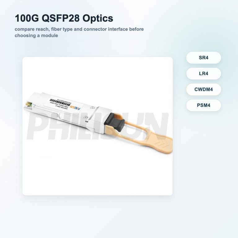
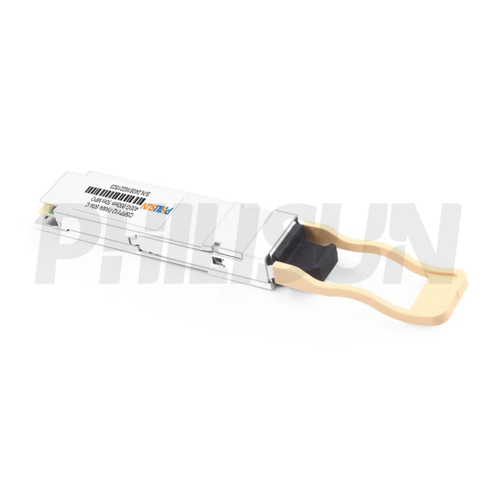
Pluggable optics are the normal choice when a link needs structured fiber cabling, isolation between equipment rows or a reach beyond practical copper. Start with the required PMD or module specification, not only the QSFP112 shell. Confirm multimode versus single-mode fiber, connector, wavelength plan, reach, transmit/receive specifications and FEC requirements. PHILISUN’s optical transceiver families provide the broader product path, while the 400G QSFP112 transceiver category narrows the form factor.
For an existing fiber plant, inspect more than the nominal fiber type. Confirm end-face condition, polarity, installed connector, patch-panel loss and the total channel budget. Parallel multimode links and wavelength-multiplexed single-mode links can both appear under the same 400G speed label while requiring entirely different trunks and patch cords. Cleaning and power measurement should be part of acceptance when the link is installed.
Direct-attach copper
A passive DAC is attractive for short, point-to-point links because it has no optical conversion and typically minimizes component count. But cable length, wire gauge, host loss budget and port configuration are part of the design. A breakout DAC also requires the host to support the requested lane split; a connector branch alone cannot create breakout capability.
Active optical cables
An AOC provides a factory-terminated optical link and can simplify installation when a fixed cable assembly is acceptable. It is less field-serviceable than two transceivers and a replaceable fiber patch cord. Review bend radius, pulling path, endpoint form factors and host coding before choosing between DAC and AOC cable families.
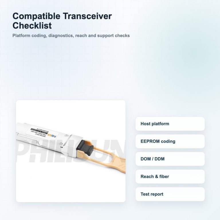
The eight-point QSFP112 compatibility checklist
1–4: host and link requirements
- Host port: record the switch, router, NIC or accelerator model, hardware revision and exact port type.
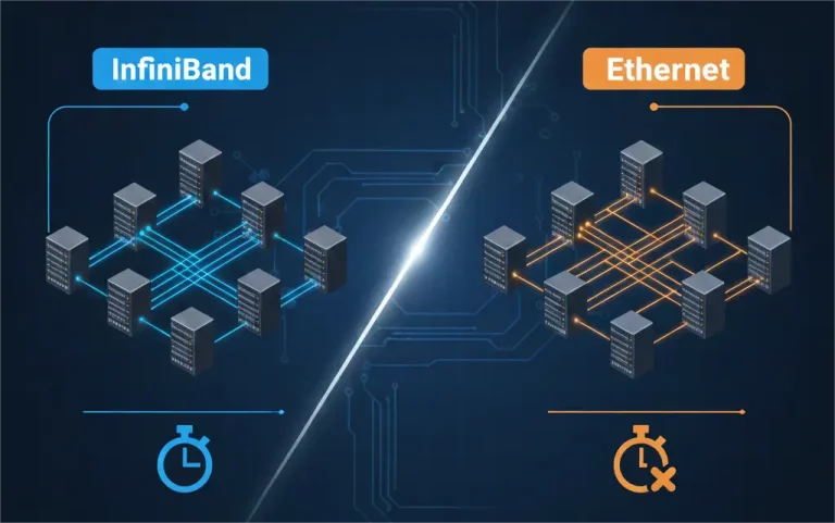
- Speed and protocol: specify Ethernet or InfiniBand, the desired port speed and any breakout mode. A 400G label does not prove the same protocol or lane mapping.
- Media and reach: state DAC, AOC, multimode or single-mode fiber and the real path length, including patch panels and service loops.
- Optical interface: for optics, confirm the PMD/module type, wavelength plan, fiber count, polarity and connector.
5–8: platform and operating environment
- Coding and allow-list behavior: identify the platform vendor and software release. Some hosts warn, limit or reject unrecognized modules; read the guide to compatible optical transceivers for the wider process.
- Management and diagnostics: verify that the host and module agree on required memory-map, monitoring and control behavior. A current specification revision on paper does not guarantee that every deployed platform implements it.
- FEC and link configuration: check the host’s required FEC, autonegotiation and lane settings for the selected module or cable. Do not assume defaults match at both ends.
- Thermal and airflow conditions: record ambient range, front-to-back or back-to-front airflow, cage/heatsink arrangement and adjacent-port loading. Validate the specific module power class with the platform.
If any one of these inputs is unknown, treat the selection as provisional. “It fits” is evidence for only the mechanical layer.
Common deployment scenarios
Native 400G switch-to-switch or switch-to-NIC
For a native 400G link, confirm both endpoints expose the same protocol, lane architecture and supported module type. Then choose the optical PMD or cable according to distance and infrastructure. A short multimode example may use a 400G QSFP112 SR4 module, but its fiber and reach specifications must be matched at both ends.
Breakout to lower-speed ports
A QSFP112-side cable can fan out to lower-speed endpoints only when the host ASIC, port configuration and software support that split. Confirm which parent lanes map to each child port, whether all branches use the same protocol, and whether the cable endpoint form factor is correct. For InfiniBand context, the distinction between NDR and HDR InfiniBand is separate from the physical connector decision.
Mixed-form-factor links
A QSFP112 endpoint may connect to a different form factor through a purpose-built cable or transceiver pair, but the entire link still needs a common electrical/optical interface and protocol. Never infer interoperability from “400G” on both product names. Validate each endpoint, the center media and the desired lane mode as one system.
A practical selection workflow
- Copy the exact part number and software version for both hosts.
- Confirm native speed, protocol and supported breakout modes in the host documentation.
- Choose DAC, AOC or optics from actual distance and cabling constraints.
- For optics, select the PMD, connector and fiber plant; for cables, select endpoint form factors and length.
- Check vendor coding, diagnostics, management behavior, FEC and lane configuration.
- Review thermal limits and airflow at realistic adjacent-port loading.
- Request written compatibility confirmation and test the link before a volume rollout.
This order prevents a common failure mode: selecting a low-cost module by speed and reach, then discovering late that the host port, firmware or lane mode is different.
For a pilot, record module serial number, host ports, software version, configured speed/FEC, transmit and receive levels where available, temperature, error counters and link-flap history. Repeat the check after the equipment reaches normal operating temperature and with realistic adjacent-port loading. This creates a repeatable acceptance record for the volume order and gives engineering useful evidence if a later firmware or topology change affects the link.
QSFP112 FAQ
Is QSFP112 always 400G?
QSFP112 is designed around four 112G-class host lanes for a 400G interconnect ecosystem. The actual operational speed and protocol depend on the module, host and configuration. Verify the complete link rather than relying on the form-factor name.
Can a QSFP112 module plug into a QSFP-DD port?
Some QSFP-DD systems are designed to accept four-lane QSFP-family modules, but acceptance and operation depend on the specific cage generation, host ASIC, firmware and supported speed mode. Treat the platform compatibility matrix as authoritative.
Is QSFP112 the same as OSFP?
No. QSFP112 is a four-lane QSFP-family system, while OSFP is an eight-lane form-factor family with different mechanics. A supported adapter or cable may bridge specific applications, but the modules are not the same form factor.
Should I choose a QSFP112 DAC or optical transceiver?
Use a validated DAC for short direct links when its length and host loss budget fit. Choose an AOC for a fixed, lightweight optical assembly, or pluggable optics when you need structured fiber, replaceable components or longer reach. Host approval and lane mode remain mandatory in every case.
Verify the link before ordering
Send PHILISUN the two host models, software versions, speed/protocol, required reach, cable or fiber type, connector, airflow direction and coding requirements. We can map those inputs to a candidate module or cable and identify what still needs lab validation. Request a QSFP112 compatibility check.